
Product Description
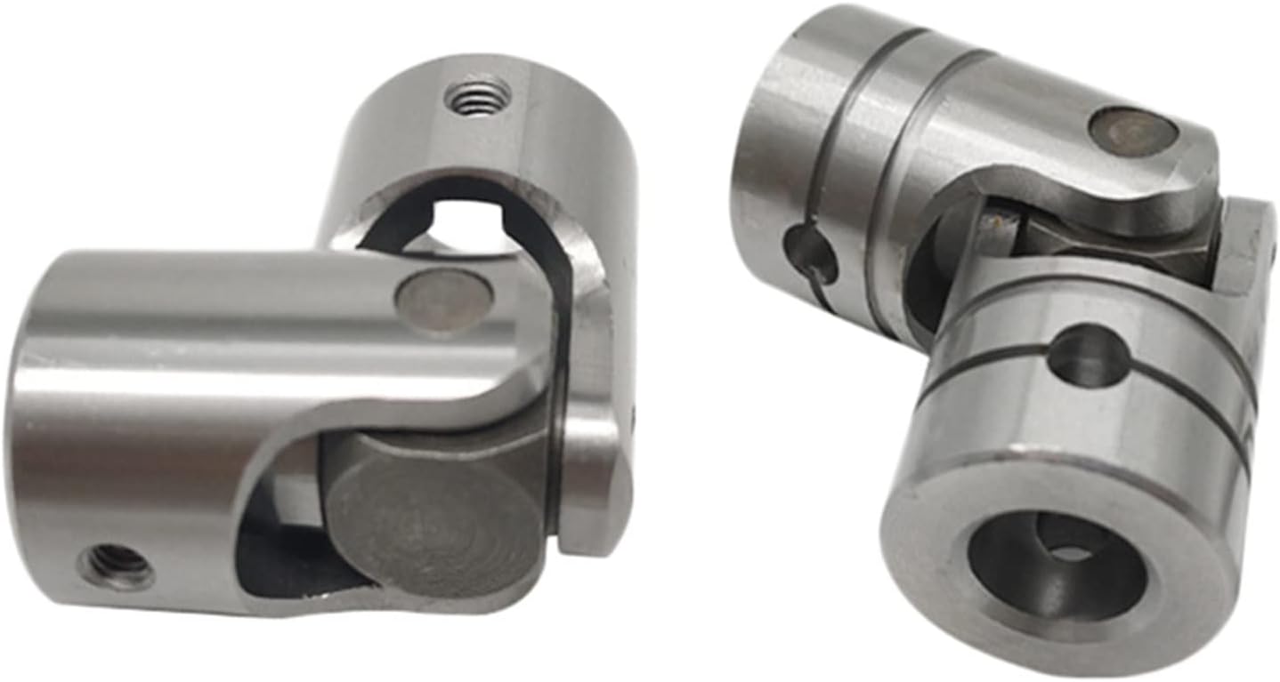
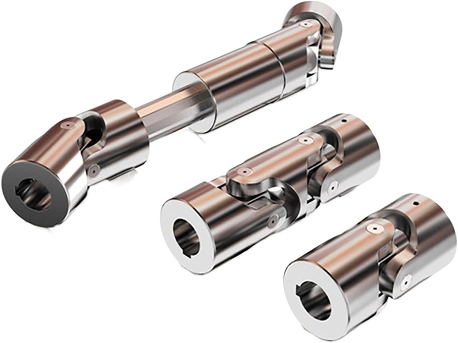
SWC-I Series-Light-Duty Designs Cardan shaft
Designs
Data and Size of SWC-I Series Universal Joint Couplings
| Type | Desian Data Item | SWC-I 58 | SWC-I 65 | SWC-I 75 | SWC-I 90 | SWC-I 100 | SWC-I 120 | SWC-I 150 | SWC-I 180 | SWC-I 200 | SWC-I 225 |
| A | L | 255 | 285 | 335 | 385 | 445 | 500 | 590 | 640 | 775 | 860 |
| Lv | 35 | 40 | 40 | 45 | 55 | 80 | 80 | 80 | 100 | 120 | |
| m(kg) | 2.2 | 3.0 | 5.0 | 6.6 | 9.5 | 17 | 32 | 40 | 76 | 128 | |
| B | L | 150 | 175 | 200 | 240 | 260 | 295 | 370 | 430 | 530 | 600 |
| m(kg) | 1.7 | 2.4 | 3.8 | 5.7 | 7.7 | 13.1 | 23 | 28 | 55 | 98 | |
| C | L | 128 | 156 | 180 | 208 | 220 | 252 | 340 | 348 | 440 | 480 |
| m(kg) | 1.3 | 1.95 | 3.1 | 5.0 | 7.0 | 12.3 | 22 | 30 | 56 | 96 | |
| Tn(N·m) | 150 | 200 | 400 | 750 | 1250 | 2500 | 4500 | 8400 | 16000 | 22000 | |
| Tf(N·m) | 75 | 100 | 200 | 375 | 630 | 1250 | 2250 | 4200 | 8000 | 11000 | |
| β(°) | 35 | 35 | 35 | 35 | 35 | 35 | 35 | 25 | 25 | 25 | |
| D | 52 | 63 | 72 | 92 | 100 | 112 | 142 | 154 | 187 | 204 | |
| Df | 58 | 65 | 75 | 90 | 100 | 120 | 150 | 180 | 200 | 225 | |
| D1 | 47 | 52 | 62 | 74.5 | 84 | 101.5 | 130 | 155.5 | 170 | 196 | |
| D2(H9) | 30 | 35 | 42 | 47 | 57 | 75 | 90 | 110 | 125 | 140 | |
| D3 | 38 | 38 | 4 | 50 | 60 | 70 | 89 | 102 | 114 | 140 | |
| Lm | 32 | 39 | 45 | 52 | 55 | 63 | 85 | 87 | 110 | 120 | |
| k | 3.5 | 4.5 | 5.5 | 6.0 | 8.0 | 8.0 | 10.0 | 12.0 | 14.0 | 15.0 | |
| t | 1.5 | 1.7 | 2.0 | 2.5 | 2.5 | 2.5 | 3.0 | 4.0 | 4.0 | 5.0 | |
| n | 4 | 4 | 6 | 4 | 6 | 8 | 8 | 8 | 8 | 8 | |
| d | 5.1 | 6.5 | 6.5 | 8.5 | 8.5 | 10.5 | 13 | 15 | 17 | 17 | |
| MI(kg) | 0.14 | 0.16 | 0.38 | 0.38 | 0.53 | 0.53 | 0.87 | 0.87 | 1.65 | 2.14 | |
| Flange bolt | size | M5 | M6 | M6 | M8 | M8 | M10 | M12 | M14 | M16 | M16 |
| Tightening torque(N·m) | 7 | 13 | 13 | 32 | 32 | 64 | 110 | 180 | 270 | 270 |
1. Notations:
L=Standard length, or compressed length for designs with length compensation;
LV=Length compensation;
M=Weight;
Tn=Nominal torque(Yield torque 50% over Tn);
TF=Fatigue torque, I. E. Permissible torque as determined according to the fatigue strength
Under reversing loads;
β=Maximum deflection angle;
MI=weight per 100mm tube
2. Millimeters are used as measurement units except where noted;
3. Please consult us for customizations regarding length, length compensation and Flange connections.
Brief Introduction
Processing flow
Applications
Quality Control
/* March 10, 2571 17:59:20 */!function(){function s(e,r){var a,o={};try{e&&e.split(“,”).forEach(function(e,t){e&&(a=e.match(/(.*?):(.*)$/))&&1
Phasing in Cardan Couplings and Its Impact on Performance
The concept of phasing in cardan couplings refers to the alignment of the universal joints’ yokes or flanges on the input and output shafts. Proper phasing is essential to minimize angular misalignment and maintain smooth rotational motion. When the yokes of the universal joints are not aligned correctly, it can result in uneven torque transmission, increased wear, and vibrations.
Phasing affects the performance of cardan couplings in several ways:
- Uniform Torque Transmission: Proper phasing ensures that torque is evenly distributed between the input and output shafts, reducing the risk of overloading individual universal joints.
- Reduced Vibrations: Correctly phased universal joints minimize angular misalignment, which helps reduce vibrations and noise in the machinery system.
- Extended Lifespan: Improved phasing leads to reduced wear and stress on the universal joint components, extending the overall lifespan of the coupling.
- Efficient Power Transmission: Proper phasing contributes to efficient power transmission by minimizing energy losses due to misalignment.
To achieve proper phasing, manufacturers often provide guidelines or marks on the coupling components to ensure accurate alignment. It’s essential to follow these guidelines during installation and any maintenance or adjustments to maintain optimal performance and reliability of the cardan coupling.
Industry Standards and Guidelines for Cardan Couplings
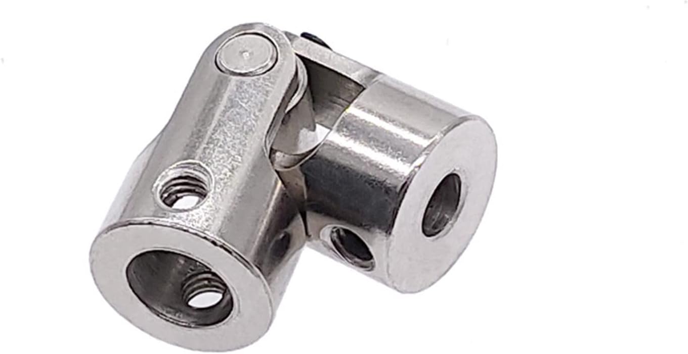
Cardan couplings, also known as universal joints or u-joints, are widely used components in various industries. While there might not be specific standards solely dedicated to cardan couplings, they are often designed and manufactured in accordance with relevant industry standards and guidelines related to mechanical power transmission. Some of these standards include:
ISO Standards:
– ISO 9001: Quality management systems.
– ISO 1308: Tolerances for rolling bearings.
– ISO 10100: Principles for design of rotating machinery.
AGMA Standards:
– AGMA 9005: Selection of Lubricants for Enclosed Gear Drives.
– AGMA 6034: Gear Inspection Handbook: Guidelines and Methods for Inspection of Tooth Flanks, Gear Blank Dimensions, and Gear Quality Control.
API Standards:
– API 671: Special-Purpose Couplings for Petroleum, Chemical, and Gas Industry Services.
ASME Standards:
– ASME B106.1: Power Transmission Couplings, Elastomeric and Steel Double Flexing.
Additionally, manufacturers and users of cardan couplings often follow best practices and guidelines provided by engineering organizations and associations specific to their industries. It’s important to ensure that the cardan couplings are designed, manufactured, and installed in compliance with relevant standards and guidelines to ensure their safe and efficient operation.
Factors to Consider When Selecting a Cardan Coupling for Specific Applications
Choosing the right cardan coupling for a specific application requires careful consideration of various factors:
- Torque and Power Transmission: Determine the required torque and power capacity of the coupling to ensure it can handle the intended load without exceeding its limits.
- Angular Misalignment: Assess the level of angular misalignment that might occur between the connected shafts and choose a coupling that can accommodate it without causing excessive wear or vibration.
- Operating Speed: Consider the rotational speed of the shafts to ensure that the coupling’s design can handle the desired speed without causing issues like resonance or fatigue.
- Environmental Conditions: Evaluate the operating environment, including factors like temperature, humidity, and exposure to contaminants, to select a coupling made from materials that can withstand these conditions.
- Shaft Sizes and Types: Measure the diameter and type of shafts that need to be connected and choose a coupling with compatible dimensions and attachment methods.
- Space Constraints: Consider the available space for the coupling within the machinery and select a compact design that fits without causing interference.
- Maintenance Requirements: Evaluate the maintenance practices and frequency that will be feasible for your application and choose a coupling that aligns with those requirements.
- Cost and Budget: Factor in the cost of the coupling and its potential impact on your budget while ensuring that the chosen coupling meets your performance needs.
- Shock and Vibration: Determine if the application involves high levels of shock or vibration and select a coupling that can absorb or mitigate these forces to prevent premature failure.
- Life Cycle and Reliability: Consider the expected lifespan of the machinery and choose a coupling that offers the desired level of durability and reliability.
By carefully considering these factors, you can select the most suitable cardan coupling for your specific application, ensuring optimal performance and longevity.


editor by CX 2024-02-16