Product Description
Product Description
Product Description
SWC BH Cardan Shaft Basic Parameter And Main Dimension
Cardan shaft is widely used in rolling mill, punch, straightener, crusher, ship drive, paper making equipment, common machinery, water pump equipment, test bench, and other mechanical applications.
Advantage:
1. Low life-cycle costs and long service life;
2. Increase productivity;
3. Professional and innovative solutions;
4. Reduce carbon dioxide emissions, and environmental protection;
5. High torque capacity even at large deflection angles;
6. Easy to move and run smoothly;
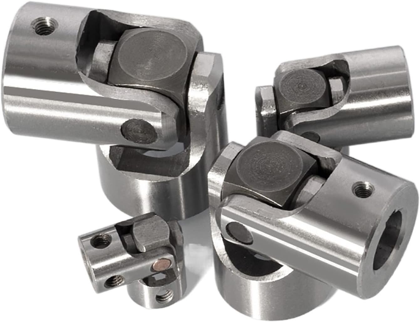
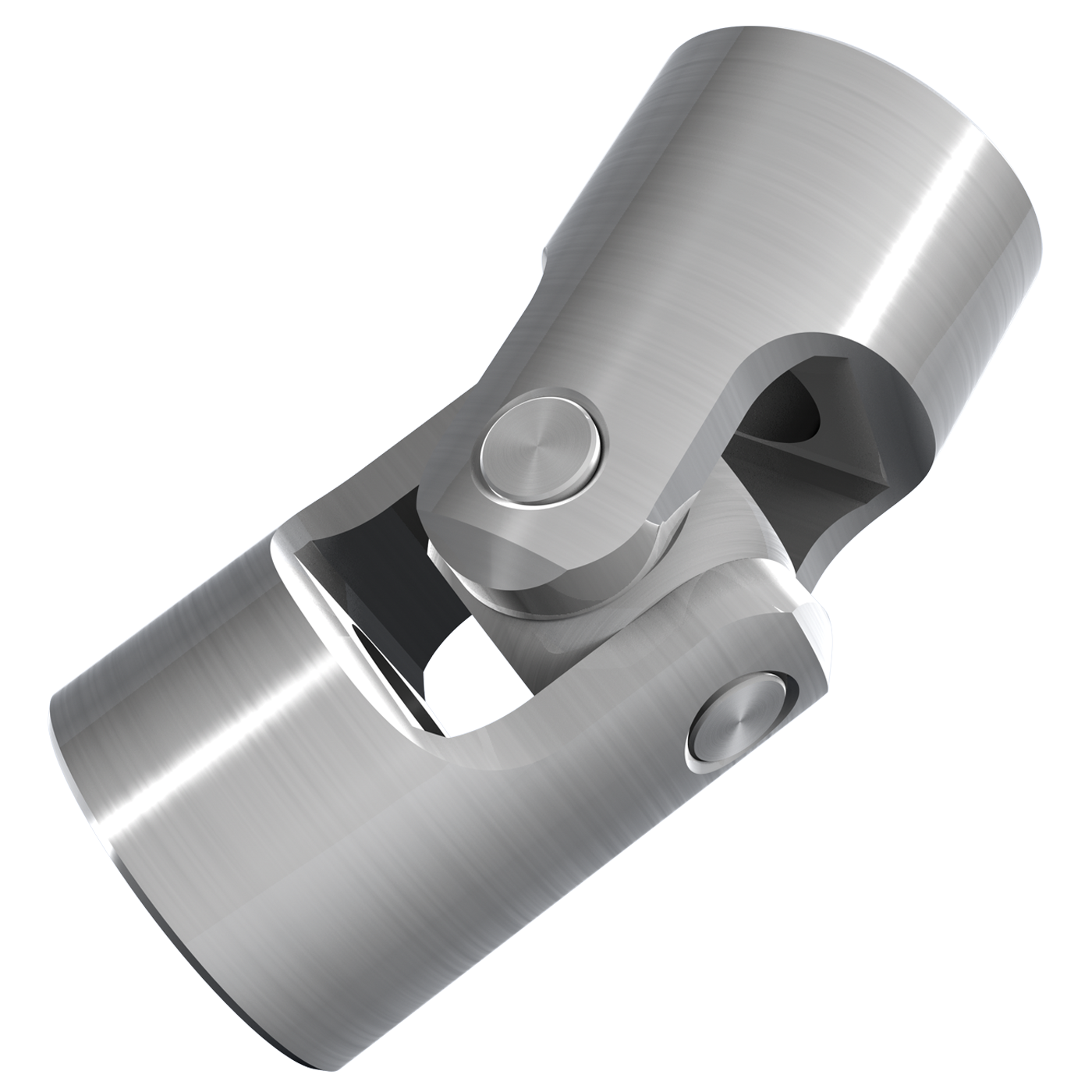
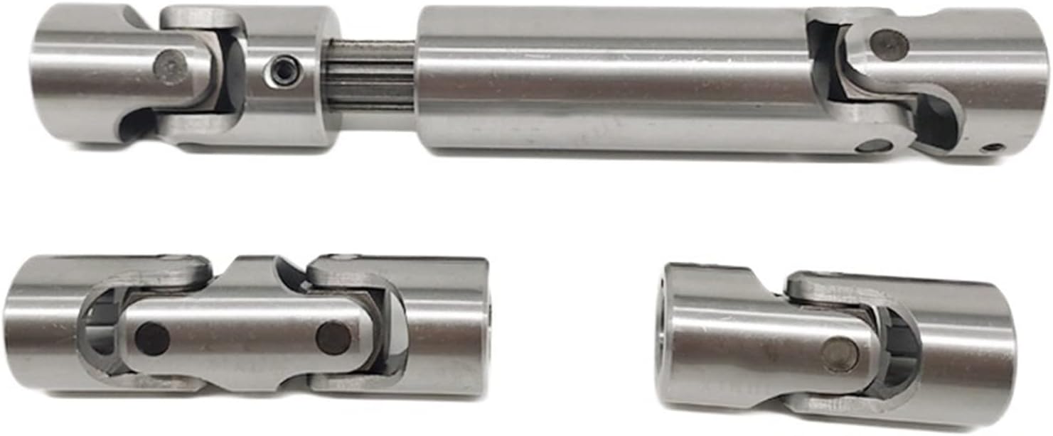
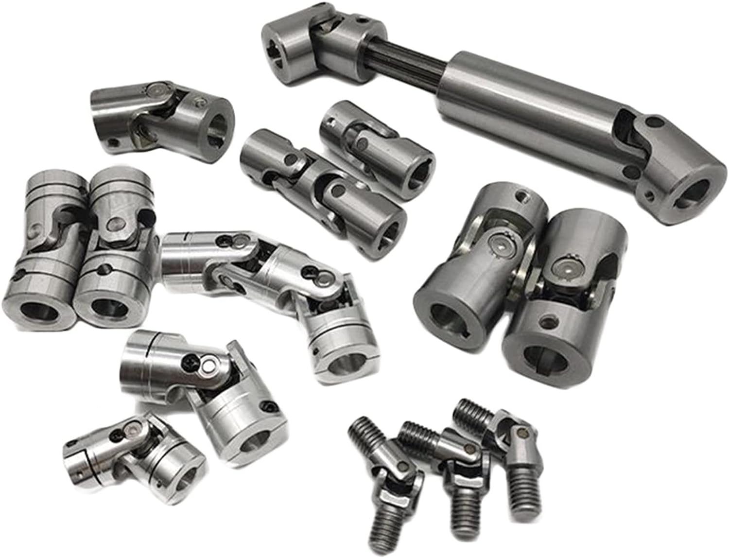
Detailed Photos
Product Parameters
| Model | Tn kN • m |
T. |
p (.) |
LS mm |
Lmin | Size mm |
I kg. m2 | m kg |
|||||||||||
| Di js11 |
d2 H7 |
Da | Lm | n-d | k | t | b h9 |
g | Lmin | 100mm | Lmin | 100mm | |||||||
| SWC58BH | 58 | 0.15 | 0.075 | ≤22 | 35 | 325 | 47 | 30 | 38 | 35 | 4-5 | 3.5 | 1.5 | – | – | – | – | 2.2 | – |
| SWC65BH | 65 | 0.25 | 0.125 | ≤22 | 40 | 360 | 52 | 35 | 42 | 46 | 4-6 | 4.5 | 1.7 | – | – | – | – | 3.0 | – |
| SWC75BH | 75 | 0.50 | 0.25 | ≤22 | 40 | 395 | 62 | 42 | 50 | 58 | 6-6 | 5.5 | 2.0 | – | – | – | – | 5.0 | – |
| SWC90BH | 90 | 1.0 | 0.50 | ≤22 | 45 | 435 | 74.5 | 47 | 54 | 58 | 4-8 | 6.0 | 2.5 | – | – | – | – | 6.6 | – |
| SWC100BH | 100 | 1.5 | 0.75 | ≤25 | 55 | 390 | 84 | 57 | 60 | 58 | 6-9 | 7 | 2.5 | – | – | 0.0044 | 0.00019 | 6.1 | 0.35 |
| SWC120BH | 120 | 2.5 | 1.25 | ≤25 | 80 | 485 | 102 | 75 | 70 | 68 | 8-11 | 8 | 2.5 | – | – | 0.5719 | 0.00044 | 10.8 | 0.55 |
| SWC150BH | 150 | 5 | 2.5 | ≤25 | 80 | 590 | 13.0 | 90 | 89 | 80 | 8-13 | 10 | 3.0 | – | – | 0.0423 | 0.00157 | 24.5 | 0.85 |
| SWC160BH | 160 | 10 | 5 | ≤25 | 80 | 660 | 137 | 100 | 95 | 110 | 8-15 | 15 | 3.0 | 20 | 12 | 0.1450 | 0.0060 | 68 | 1.72 |
| SWC180BH | 180 | 20 | 10 | ≤25 | 100 | 810 | 155 | 105 | 114 | 130 | 8-17 | 17 | 5.0 | 24 | 14 | 0.1750 | 0.0070 | 70 | 2.8 |
| SWC200BH | 200 | 32 | 16 | ≤15 | 110 | 860 | 170 | 120 | 127 | 135 | 8-17 | 19 | 5.0 | 28 | 16 | 0.3100 | 0.0130 | 86 | 3.6 |
| SWC225BH | 225 | 40 | 20 | ≤15 | 140 | 920 | 196 | 135 | 152 | 120 | 8-17 | 20 | 5.0 | 32 | 9.0 | 0.5380 | 0.5714 | 122 | 4.9 |
| SWC250BH | 250 | 63 | 31.5 | ≤15 | 140 | 1035 | 218 | 150 | 168 | 140 | 8-19 | 25 | 6.0 | 40 | 12.5 | 0.9660 | 0.5717 | 172 | 5.3 |
| SWC285BH | 285 | 90 | 45 | ≤15 | 140 | 1190 | 245 | 170 | 194 | 160 | 8-21 | 27 | 7.0 | 40 | 15.0 | 2.0110 | 0.571 | 263 | 6.3 |
| SWC315BH | 315 | 125 | 63 | ≤15 | 140 | 1315 | 280 | 185 | 219 | 180 | 10-23 | 32 | 8.0 | 40 | 15.0 | 3.6050 | 0.571 | 382 | 8.0 |
| SWC350BH | 350 | 180 | 90 | ≤15 | 150 | 1410 | 310 | 210 | 267 | 194 | 10-23 | 35 | 8.0 | 50 | 16.0 | 7.571 | 0.2219 | 582 | 15.0 |
| SWC390BH | 390 | 250 | 125 | ≤15 | 170 | 1590 | 345 | 235 | 267 | 215 | 10-25 | 40 | 8.0 | 70 | 18.0 | 12.164 | 0.2219 | 738 | 15.0 |
| SWC440BH | 440 | 355 | 180 | ≤15 | 190 | 1875 | 390 | 255 | 325 | 260 | 16-28 | 42 | 10 | 80 | 20.0 | 21.420 | 0.4744 | 1190 | 21.7 |
| SWC490BH | 490 | 500 | 250 | ≤15 | 190 | 1985 | 435 | 275 | 325 | 270 | 16-31 | 47 | 12 | 90 | 22.5 | 32.860 | 0.4744 | 1452 | 21.7 |
| SWC550BH | 550 | 710 | 355 | ≤15 | 240 | 2300 | 492 | 320 | 426 | 305 | 16-31 | 50 | 12 | 100 | 22.5 | 68.920 | 1.3570 | 2380 | 34 |
Packaging & Shipping
Company Profile
HangZhou CHINAMFG Machinery Manufacturing Co., Ltd. is a high-tech enterprise specializing in the design and manufacture of various types of coupling. There are 86 employees in our company, including 2 senior engineers and no fewer than 20 mechanical design and manufacture, heat treatment, welding, and other professionals.
Advanced and reasonable process, complete detection means. Our company actively introduces foreign advanced technology and equipment, on the basis of the condition, we make full use of the advantage and do more research and innovation. Strict to high quality and operate strictly in accordance with the ISO9000 quality certification system standard mode.
Our company supplies different kinds of products. High quality and reasonable price. We stick to the principle of “quality first, service first, continuous improvement and innovation to meet the customers” for the management and “zero defect, zero complaints” as the quality objective.
Our Services
1. Design Services
Our design team has experience in Cardan shafts relating to product design and development. If you have any needs for your new product or wish to make further improvements, we are here to offer our support.
2. Product Services
raw materials → Cutting → Forging →Rough machining →Shot blasting →Heat treatment →Testing →Fashioning →Cleaning→ Assembly→Packing→Shipping
3. Samples Procedure
We could develop the sample according to your requirement and amend the sample constantly to meet your need.
4. Research & Development
We usually research the new needs of the market and develop new models when there are new cars in the market.
5. Quality Control
Every step should be a particular test by Professional Staff according to the standard of ISO9001 and TS16949.
FAQ
Q 1: Are you a trading company or a manufacturer?
A: We are a professional manufacturer specializing in manufacturing
various series of couplings.
Q 2:Can you do OEM?
Yes, we can. We can do OEM & ODM for all customers with customized PDF or AI format artwork.
Q 3:How long is your delivery time?
Generally, it is 20-30 days if the goods are not in stock. It is according to quantity.
Q 4: Do you provide samples? Is it free or extra?
Yes, we could offer the sample but not for free. Actually, we have an excellent price principle, when you make the bulk order the cost of the sample will be deducted.
Q 5: How long is your warranty?
A: Our Warranty is 12 months under normal circumstances.
Q 6: What is the MOQ?
A: Usually our MOQ is 1pcs.
Q 7: Do you have inspection procedures for coupling?
A:100% self-inspection before packing.
Q 8: Can I have a visit to your factory before the order?
A: Sure, welcome to visit our factory.
Q 9: What’s your payment?
A:1) T/T.
♦Contact Us
Web: huadingcoupling
Add: No.11 HangZhou Road,Chengnan park,HangZhou City,ZheJiang Province,China
Diagnosing and Troubleshooting Cardan Coupling Issues
Diagnosing and troubleshooting issues related to cardan couplings in machinery systems involves a systematic approach:
- Visual Inspection: Examine the cardan coupling for signs of wear, damage, misalignment, or corrosion. Look for any unusual noises or vibrations.
- Check Lubrication: Inspect the lubrication system and ensure proper lubricant levels. Inadequate lubrication can lead to premature wear.
- Monitor Performance: Use sensors and monitoring systems to track the performance of the cardan coupling in real-time. Analyze data for anomalies.
- Measure Alignment: Check for proper alignment between the input and output shafts. Misalignment can lead to increased wear and reduced efficiency.
- Check for Unusual Noises: Listen for any unusual noises during operation, such as grinding, squeaking, or knocking sounds.
- Inspect Components: Examine the individual components of the cardan coupling, including the universal joints and shafts, for signs of wear or damage.
- Perform Load Analysis: Evaluate the operating conditions and loads to ensure they are within the specified limits of the cardan coupling.
- Review Maintenance Records: Refer to maintenance records to ensure that the cardan coupling has been properly maintained and serviced.
- Consult Manufacturer Guidelines: Follow the manufacturer’s guidelines for troubleshooting and diagnostics specific to the cardan coupling model.
By following these steps, operators and maintenance personnel can effectively diagnose and troubleshoot cardan coupling issues, ensuring the reliable and efficient operation of machinery systems.
Comparison of Cardan Couplings with Other Flexible Couplings
Cardan couplings, universal joints, and gear couplings are all types of flexible couplings used to transmit torque while accommodating misalignment. Here’s how a cardan coupling compares to other flexible coupling types:
1. Cardan Couplings:
– Also known as shaft couplings or u-joints.
– Typically consist of two yokes connected by a cross-shaped component called a spider.
– Accommodate angular misalignment.
– Limited to relatively lower speeds and torques.
– Provide moderate torsional flexibility.
2. Universal Joints:
– Consist of two yokes connected by cross-shaped pins and bearings.
– Accommodate angular misalignment similar to cardan couplings.
– Can transmit higher torques than cardan couplings.
– Limited in their ability to handle axial and parallel misalignment.
– Used in various applications, including automotive and industrial equipment.
3. Gear Couplings:
– Feature toothed gears that mesh to transmit torque.
– Accommodate angular, axial, and parallel misalignment.
– Suitable for high-speed and high-torque applications.
– Provide high torsional rigidity and accurate torque transmission.
– Require proper lubrication and maintenance.
When comparing these coupling types:
– Cardan couplings are simple and cost-effective solutions for moderate torque and speed applications with angular misalignment.
– Universal joints are versatile but may have limitations in handling higher torques and other misalignment types.
– Gear couplings offer superior torque and misalignment handling but are more complex and may require more maintenance.
The choice of coupling type depends on the specific application’s torque, speed, misalignment, and precision requirements.
What are the key features and benefits of using a cardan coupling?
Cardan couplings, also known as universal joints or U-joints, offer several key features and benefits that make them valuable components in various mechanical systems:
- Angular Misalignment Compensation: One of the primary features of cardan couplings is their ability to accommodate angular misalignment between shafts. This flexibility allows them to transmit torque even when the input and output shafts are not collinear.
- Torque Transmission: Cardan couplings are effective in transmitting torque between shafts at an angle. They can handle both small and moderate torque loads, making them suitable for a wide range of applications.
- Compact Design: The simple and compact design of cardan couplings makes them easy to integrate into various mechanical systems without requiring excessive space.
- Cost-Effective Solution: Cardan couplings provide a cost-effective solution for transmitting torque in cases of angular misalignment. Their straightforward design and manufacturing process contribute to their affordability.
- High-Speed Transmission: Cardan couplings can handle high rotational speeds, making them suitable for applications where rapid motion and torque transmission are required.
- Versatility: These couplings find applications in diverse industries, including automotive, industrial machinery, agriculture, and aerospace, due to their ability to compensate for misalignment and transmit torque effectively.
- Reduced Vibrations: In some cases, cardan couplings can help dampen vibrations and shocks that may occur due to misalignment, contributing to smoother operation.
- Simple Maintenance: Maintenance of cardan couplings typically involves lubrication of the bearing and regular inspection for wear and tear. This maintenance process is relatively straightforward and can extend the component’s lifespan.
- Easy Replacement: If a cardan coupling needs to be replaced due to wear or failure, its simple design makes the replacement process relatively quick and uncomplicated.
Overall, the key features and benefits of using cardan couplings make them an attractive choice for applications where torque transmission and angular misalignment compensation are necessary.


editor by CX 2023-11-16
China OEM Telescopic Cardan Shaft Telescopic Universal Joint Shaft Coupling
Product Description
Short Telescopic Welding Cardan Shaft Coupling (SWC DH)
SWC-DH type cross shaft universal coupling is 1 of the most commonly used coupling. The characteristics of the structure can not in the same axis or axis angle or larger axial movement of 2 large equiangular continuous rotary speed, and reliably transfer torque and motion. Can be widely used in metallurgy, lifting, transportation, mining, petroleum, shipbuilding, coal, rubber, paper machinery and other heavy machinery industry machinery shaft in the transmission torque.
The main features of SWC-DH type cross shaft universal coupling:
1. has a large angle compensation ability.
2. compact and reasonable structure. The SWC-DH type uses the integral fork head, causes the vehicle to have more reliable.
3 .carrying capacity.
4. high transmission efficiency. Its transmission efficiency up to 98-99.8%, used for large power transmission, energy saving effect is obvious.
5 .carry a smooth, low noise, easy to install and maintenance.
·SWC DH Cardan Shaft Basic Parameter And Main Dimension(JB/T5513-1991)
| Model | Tactical diameter D mm |
Nominal torque Tn kN·m |
Fatique torque Tf kN·m |
Axis rotation β (°) |
Stretch length LS mm |
Lmin | Size mm |
Rotary inertia kg.m2 |
Weight kg |
||||||||||
| D1 js11 |
D2 H7 |
D3 | Lm | n-d | k | t | b h9 |
g | Lmin | Increase 100mm |
Lmin | Increase 100mm |
|||||||
| SWC180DH1 | 180 | 20 | 10 | ≤25 | 75 | 650 | 155 | 105 | 114 | 110 | 8-17 | 17 | 5 | 24 | 7 | 0.165 | 0.0070 | 58 | 2.8 |
| SWC180DH2 | 55 | 600 | 0.162 | 56 | |||||||||||||||
| SWC180DH3 | 40 | 550 | 0.160 | 52 | |||||||||||||||
| SWC200DH1 | 200 | 32 | 16 | ≤15 | 80 | 720 | 170 | 120 | 127 | 135 | 8-17 | 19 | 5 | 28 | 16 | 0.276 | 0.0130 | 76 | 3.6 |
| SWC200DH2 | 50 | 690 | 0.261 | 74 | |||||||||||||||
| SWC225DH1 | 225 | 40 | 20 | ≤15 | 85 | 710 | 196 | 135 | 152 | 120 | 8-17 | 20 | 5 | 32 | 9.0 | 0.415 | 0.5714 | 95 | 4.9 |
| SWC225DH2 | 70 | 640 | 0.397 | 92 | |||||||||||||||
| SWC250DH1 | 250 | 63 | 31.5 | ≤15 | 100 | 795 | 218 | 150 | 168 | 140 | 8-19 | 25 | 6 | 40 | 12.5 | 0.900 | 0.5717 | 148 | 5.3 |
| SWC250DH2 | 70 | 735 | 0.885 | 136 | |||||||||||||||
| SWC285DH1 | 285 | 90 | 45 | ≤15 | 120 | 950 | 245 | 170 | 194 | 160 | 8-21 | 27 | 7 | 40 | 15.0 | 1.826 | 0.571 | 229 | 6.3 |
| SWC285DH2 | 80 | 880 | 1.801 | 221 | |||||||||||||||
| SWC315DH1 | 315 | 125 | 63 | ≤15 | 130 | 1070 | 280 | 185 | 219 | 180 | 10-23 | 32 | 8 | 40 | 15.0 | 3.331 | 0.571 | 346 | 8.0 |
| SWC315DH2 | 90 | 980 | 3.163 | 334 | |||||||||||||||
| SWC350DH1 | 350 | 180 | 90 | ≤15 | 140 | 1170 | 310 | 210 | 267 | 194 | 10-23 | 35 | 8 | 50 | 16.0 | 6.215 | 0.2219 | 508 | 15.0 |
| SWC350DH2 | 90 | 1070 | 5.824 | 485 | |||||||||||||||
| SWC390DH1 | 390 | 250 | 125 | ≤15 | 150 | 1300 | 345 | 235 | 267 | 215 | 10-25 | 40 | 8 | 70 | 18.0 | 11.125 | 0.2219 | 655 | 15.0 |
| SWC390DH2 | 90 | 1200 | 10.763 | 600 | |||||||||||||||
·Note:1.Tf-Torque allowed by fatigue strength under varible load
2.Lmin-Minimum length after shortening
3.L-Installation length as required
Detailed Photos
Packaging & Shipping
Company Profile
HangZhou CHINAMFG Machinery Manufacturing Co., Ltd. is a high-tech enterprise specializing in the design and manufacture of various types of coupling. There are 86 employees in our company, including 2 senior engineers and no fewer than 20 mechanical design and manufacture, heat treatment, welding, and other professionals.
Advanced and reasonable process, complete detection means. Our company actively introduces foreign advanced technology and equipment, on the basis of the condition, we make full use of the advantage and do more research and innovation. Strict to high quality and operate strictly in accordance with the ISO9000 quality certification system standard mode.
Our company supplies different kinds of products. High quality and reasonable price. We stick to the principle of “quality first, service first, continuous improvement and innovation to meet the customers” for the management and “zero defect, zero complaints” as the quality objective.
Our Services
1. Design Services
Our design team has experience in Cardan shafts relating to product design and development. If you have any needs for your new product or wish to make further improvements, we are here to offer our support.
2. Product Services
raw materials → Cutting → Forging →Rough machining →Shot blasting →Heat treatment →Testing →Fashioning →Cleaning→ Assembly→Packing→Shipping
3. Samples Procedure
We could develop the sample according to your requirement and amend the sample constantly to meet your need.
4. Research & Development
We usually research the new needs of the market and develop new models when there are new cars in the market.
5. Quality Control
Every step should be a particular test by Professional Staff according to the standard of ISO9001 and TS16949.
FAQ
Q 1: Are you a trading company or a manufacturer?
A: We are a professional manufacturer specializing in manufacturing
various series of couplings.
Q 2:Can you do OEM?
Yes, we can. We can do OEM & ODM for all customers with customized PDF or AI format artwork.
Q 3:How long is your delivery time?
Generally, it is 20-30 days if the goods are not in stock. It is according to quantity.
Q 4: Do you provide samples? Is it free or extra?
Yes, we could offer the sample but not for free. Actually, we have an excellent price principle, when you make the bulk order the cost of the sample will be deducted.
Q 5: How long is your warranty?
A: Our Warranty is 12 months under normal circumstances.
Q 6: What is the MOQ?
A: Usually our MOQ is 1pcs.
Q 7: Do you have inspection procedures for coupling?
A:100% self-inspection before packing.
Q 8: Can I have a visit to your factory before the order?
A: Sure, welcome to visit our factory.
Q 9: What’s your payment?
A:1) T/T.
♦Contact Us
Web: huadingcoupling
Add: No.11 HangZhou Road,Chengnan park,HangZhou City,ZheJiang Province,China
Recent Technological Advancements in Cardan Coupling Design
In recent years, there have been notable advancements and innovations in the design of cardan couplings:
- Material Enhancements: Advances in materials science have led to the development of high-strength and lightweight materials that can improve the performance and durability of cardan couplings.
- Sealing Technology: Improved sealing mechanisms and materials help prevent contamination and enhance the lifespan of cardan couplings.
- Computer-Aided Design (CAD): CAD software allows for more precise and optimized design of cardan couplings, leading to better performance and reduced stress concentrations.
- Finite Element Analysis (FEA): FEA techniques enable engineers to simulate the behavior of cardan couplings under various loads and conditions, aiding in design optimization.
- Lubrication Systems: Innovations in lubrication systems ensure efficient and consistent lubrication, reducing wear and enhancing coupling longevity.
- Monitoring and Diagnostics: Integration of sensors and monitoring systems enables real-time data collection for performance analysis, predictive maintenance, and early detection of issues.
- Customization: Advanced manufacturing techniques allow for more customization, making it possible to design cardan couplings tailored to specific applications.
These advancements contribute to the overall efficiency, reliability, and performance of cardan couplings, making them more suitable for a wide range of applications.
Handling High Torque and Axial Displacement with Cardan Couplings
Cardan couplings, also known as universal joints or u-joints, are designed to transmit torque between two shafts that are not in a straight line. They are versatile components commonly used in various applications, including those requiring high torque and axial displacement.
Handling High Torque: Cardan couplings are capable of handling high levels of torque transmission due to their robust design and construction. The design allows for torque to be transmitted through a series of interconnected components, including the cross-shaped yokes and the bearing assemblies. The use of high-strength materials and precision manufacturing techniques contributes to the coupling’s ability to transmit torque efficiently.
Handling Axial Displacement: While cardan couplings are primarily designed for accommodating angular misalignment, they can also handle a certain degree of axial displacement. Axial displacement refers to the movement of the connected shafts along their axis. However, the axial displacement capacity of a cardan coupling is limited compared to its ability to handle angular misalignment.
It’s important to note that excessive torque or axial displacement beyond the coupling’s design limits can lead to premature wear, increased vibrations, and reduced performance. Manufacturers provide specifications and guidelines for the maximum torque and axial displacement that a specific cardan coupling can handle. Engineers and designers should adhere to these specifications to ensure optimal performance and longevity of the coupling in their applications.

How do you properly install and maintain a cardan coupling in machinery?
Proper installation and maintenance of a cardan coupling are crucial to ensure its reliable performance and longevity:
- Installation:
- Align the shafts properly before connecting the coupling to minimize initial misalignment.
- Ensure that the universal joints are in phase, meaning their yokes are in the same orientation to prevent uneven torque transmission.
- Follow the manufacturer’s instructions for torque specifications while tightening bolts and fasteners to prevent overloading or loosening during operation.
- Make sure the coupling is properly centered and balanced to avoid vibrations.
- Check for any obstructions or interference that might affect the movement of the coupling.
- Maintenance:
- Regularly inspect the coupling for signs of wear, such as cracks, corrosion, or damaged components.
- Monitor the alignment of the shafts to detect any misalignment that might occur over time.
- Lubricate the universal joints and bearings as recommended by the manufacturer to reduce friction and wear.
- Replace worn or damaged components promptly to prevent further deterioration and potential coupling failure.
- Perform vibration analysis and balancing to ensure the coupling operates smoothly and doesn’t contribute to excessive vibrations in the machinery.
- Regularly check for any signs of overheating, which might indicate inadequate lubrication or other issues.
- Keep the coupling area clean from debris, dirt, and contaminants that could affect its performance.
By following proper installation procedures and conducting regular maintenance checks, you can maximize the efficiency and reliability of a cardan coupling in machinery.
editor by CX 2023-10-10
China Good quality OEM Customized CNC Aluminum Stainless Steel Machining Parts Shaft CZPT near me factory
Solution Description
Overview
Rapid Specifics
Condition:Spur Place of Origin:ZheJiang , China
Manufacturer Name:CHUNTAI Material:Stainless Steel or in accordance to customer’s demands
Certification:ISO9001:2008 Finish:Nickel plating
QC:a hundred% inspection on crucial dimensions Quality:according tolerance
Sample and Reduced MOQ:accepted Material Abilities:Aluminum, Brass, Copper,Hardened Metals,SS,Metal Alloys
Software:automotive,electrical,electronic,pump,etc OEM and ODM:yes
Procedure:Cnc milling, drilling,Pinion,Hobbing,and so on
Specification
Surface area: as your requirement
Materials: steel / aluminum / brass / iron / zinc / alloy,and many others.Any other content and dimension depends on customers’ demand from customers.
Usage: machinery
Manufacturing process: desigh,casting & machining
We are prepared to offer with sample for high quality and function testing.
We are ISO 9001: 2008 licensed organization.
Item Description
We can offer diverse sorts of Customized precision CNC machining parts.
And the material is dependent on the customers’ needs.
Aluminum Areas
Stainless steel Areas
Brass Components
Anodized areas
Plastic Components
Welcome to HangZhou Chuntai Environmental Security Mechanical Engineering Co., Ltd.
If you have project requirements,you should feel totally free to speak to me!
Products Capability
Inspection
FAQ
Q: Are you factory or trading company?
A:Truly we are a factory over 60 many years. We located in HangZhou Metropolis,ZheJiang Province,close to ZheJiang .
Q: what is your production range?
A: 1) Device:food waste disposers,drinking water treatment method plantcleaning device
2) CNC Machining parts:impellers,shaftshaft couplingsend coverflangesnuts boltsfasteners welding,etc.
Q:How long can I get some samples for checking and what about the price?
A:Normaly samples will be done within 12 days (automatic machining parts) or 35 day (cnc machining parts).
The sample cost depends on all information (size, material, finish, etc.). We will return the sample cost if your quantity is good.
Q: How is the warranty of the products quality control?
A:We hold the tightend quality controlling from very begining to the end and aim at 100% error free.
Q: What’s the Advantage of Your Components for Industry Items?
A2: Our edge is the aggressive prices, quickly shipping and substantial high quality. Our personnel are accountable-oriented, helpful-oriented,and dilient-oriented. our Industrial areas products are featured by strict tolerance, clean finish and long-daily life overall performance.
|
Customized content
|
||
|
Material available
|
Stainless stee
|
304, 304L ,316 ,316L ,430 ,201,etc
|
|
Aluminum
|
7075,6061,5052,2024,etc
|
|
|
Brass
|
H62 , H59 Steel C20, C45, C60, C35, Q235..
|
|
|
Stell Alloy
|
25CrMo, 42CrMo, 25Cr, 40Cr, Q345,11SMn30..
|
|
|
Iron Cast
|
QT600, QT250, HT450, HT150…
|
|
|
Tolerance
|
within +/-0.01mm
|
|
|
Surface treatment
|
Plating
|
3+Cr,anti-corrosion maximum 480 hours salt spray test
|
|
Coating
|
powder coating,electrial coating
|
|
|
Painting
|
Exposy painting
|
|
|
Polish
|
Satin polish,mirror polish, electrial polish
|
|
|
Anodizing
|
Hard anodizing,various color,
|
|
|
Heat treatment
|
according to drawing requirement
|
|
|
Customized content
|
||
|
Material available
|
Stainless stee
|
304, 304L ,316 ,316L ,430 ,201,etc
|
|
Aluminum
|
7075,6061,5052,2024,etc
|
|
|
Brass
|
H62 , H59 Steel C20, C45, C60, C35, Q235..
|
|
|
Stell Alloy
|
25CrMo, 42CrMo, 25Cr, 40Cr, Q345,11SMn30..
|
|
|
Iron Cast
|
QT600, QT250, HT450, HT150…
|
|
|
Tolerance
|
within +/-0.01mm
|
|
|
Surface treatment
|
Plating
|
3+Cr,anti-corrosion maximum 480 hours salt spray test
|
|
Coating
|
powder coating,electrial coating
|
|
|
Painting
|
Exposy painting
|
|
|
Polish
|
Satin polish,mirror polish, electrial polish
|
|
|
Anodizing
|
Hard anodizing,various color,
|
|
|
Heat treatment
|
according to drawing requirement
|
|
Lead Screws and Clamp Style Collars
If you have a lead screw, you’re probably interested in learning about the Acme thread on this type of shaft. You might also be interested in finding out about the Clamp style collars and Ball screw nut. But before you buy a new screw, make sure you understand what the terminology means. Here are some examples of screw shafts:
Acme thread
The standard ACME thread on a screw shaft is made of a metal that is resistant to corrosion and wear. It is used in a variety of applications. An Acme thread is available in a variety of sizes and styles. General purpose Acme threads are not designed to handle external radial loads and are supported by a shaft bearing and linear guide. Their design is intended to minimize the risk of flank wedging, which can cause friction forces and wear. The Centralizing Acme thread standard caters to applications without radial support and allows the thread to come into contact before its flanks are exposed to radial loads.
The ACME thread was first developed in 1894 for machine tools. While the acme lead screw is still the most popular screw in the US, European machines use the Trapezoidal Thread (Metric Acme). The acme thread is a stronger and more resilient alternative to square threads. It is also easier to cut than square threads and can be cut by using a single-point threading die.
Similarly to the internal threads, the metric versions of Acme are similar to their American counterparts. The only difference is that the metric threads are generally wider and are used more frequently in industrial settings. However, the metric-based screw threads are more common than their American counterparts worldwide. In addition, the Acme thread on screw shafts is used most often on external gears. But there is still a small minority of screw shafts that are made with a metric thread.
ACME screws provide a variety of advantages to users, including self-lubrication and reduced wear and tear. They are also ideal for vertical applications, where a reduced frictional force is required. In addition, ACME screws are highly resistant to back-drive and minimize the risk of backlash. Furthermore, they can be easily checked with readily available thread gauges. So, if you’re looking for a quality ACME screw for your next industrial project, look no further than ACME.
Lead screw coatings
The properties of lead screw materials affect their efficiency. These materials have high anti-corrosion, thermal resistance, and self-lubrication properties, which eliminates the need for lubrication. These coating materials include polytetrafluoroethylene (PFE), polyether ether ketone (PEK), and Vespel. Other desirable properties include high tensile strength, corrosion resistance, and rigidity.
The most common materials for lead screws are carbon steel, stainless steel, and aluminum. Lead screw coatings can be PTFE-based to withstand harsh environments and remove oil and grease. In addition to preventing corrosion, lead screw coatings improve the life of polymer parts. Lead screw assembly manufacturers offer a variety of customization options for their lead screw, including custom-molded nuts, thread forms, and nut bodies.
Lead screws are typically measured in rpm, or revolutions per minute. The PV curve represents the inverse relationship between contact surface pressure and sliding velocity. This value is affected by the material used in the construction of the screw, lubrication conditions, and end fixity. The critical speed of lead screws is determined by their length and minor diameter. End fixity refers to the support for the screw and affects its rigidity and critical speed.
The primary purpose of lead screws is to enable smooth movement. To achieve this, lead screws are usually preloaded with axial load, enabling consistent contact between a screw’s filets and nuts. Lead screws are often used in linear motion control systems and feature a large area of sliding contact between male and female threads. Lead screws can be manually operated or mortised and are available in a variety of sizes and materials. The materials used for lead screws include stainless steel and bronze, which are often protected by a PTFE type coating.
These screws are made of various materials, including stainless steel, bronze, and various plastics. They are also made to meet specific requirements for environmental conditions. In addition to lead screws, they can be made of stainless steel, aluminum, and carbon steel. Surface coatings can improve the screw’s corrosion resistance, while making it more wear resistant in tough environments. A screw that is coated with PTFE will maintain its anti-corrosion properties even in tough environments.
Clamp style collars
The screw shaft clamp style collar is a basic machine component, which is attached to the shaft via multiple screws. These collars act as mechanical stops, load bearing faces, or load transfer points. Their simple design makes them easy to install. This article will discuss the pros and cons of this style of collar. Let’s look at what you need to know before choosing a screw shaft clamp style collar. Here are some things to keep in mind.
Clamp-style shaft collars are a versatile mounting option for shafts. They have a recessed screw that fully engages the thread for secure locking. Screw shaft clamp collars come in different styles and can be used in both drive and power transmission applications. Listed below are the main differences between these two styles of collars. They are compatible with all types of shafts and are able to handle axial loads of up to 5500 pounds.
Clamp-style shaft collars are designed to prevent the screw from accidentally damaging the shaft when tightened. They can be tightened with a set screw to counteract the initial clamping force and prevent the shaft from coming loose. However, when tightening the screw, you should use a torque wrench. Using a set screw to tighten a screw shaft collar can cause it to warp and reduce the surface area that contacts the shaft.
Another key advantage to Clamp-style shaft collars is that they are easy to install. Clamp-style collars are available in one-piece and two-piece designs. These collars lock around the shaft and are easy to remove and install. They are ideal for virtually any shaft and can be installed without removing any components. This type of collar is also recommended for those who work on machines with sensitive components. However, be aware that the higher the OD, the more difficult it is to install and remove the collar.
Screw shaft clamp style collars are usually one-piece. A two-piece collar is easier to install than a one-piece one. The two-piece collars provide a more effective clamping force, as they use the full seating torque. Two-piece collars have the added benefit of being easy to install because they require no tools to install. You can disassemble one-piece collars before installing a two-piece collar.
Ball screw nut
The proper installation of a ball screw nut requires that the nut be installed on the center of the screw shaft. The return tubes of the ball nut must be oriented upward so that the ball nut will not overtravel. The adjusting nut must be tightened against a spacer or spring washer, then the nut is placed on the screw shaft. The nut should be rotated several times in both directions to ensure that it is centered.
Ball screw nuts are typically manufactured with a wide range of preloads. Large preloads are used to increase the rigidity of a ball screw assembly and prevent backlash, the lost motion caused by a clearance between the ball and nut. Using a large amount of preload can lead to excessive heat generation. The most common preload for ball screw nuts is 1 to 3%. This is usually more than enough to prevent backlash, but a higher preload will increase torque requirements.
The diameter of a ball screw is measured from its center, called the ball circle diameter. This diameter represents the distance a ball will travel during one rotation of the screw shaft. A smaller diameter means that there are fewer balls to carry the load. Larger leads mean longer travels per revolution and higher speeds. However, this type of screw cannot carry a greater load capacity. Increasing the length of the ball nut is not practical, due to manufacturing constraints.
The most important component of a ball screw is a ball bearing. This prevents excessive friction between the ball and the nut, which is common in lead-screw and nut combinations. Some ball screws feature preloaded balls, which avoid “wiggle” between the nut and the ball. This is particularly desirable in applications with rapidly changing loads. When this is not possible, the ball screw will experience significant backlash.
A ball screw nut can be either single or multiple circuits. Single or multiple-circuit ball nuts can be configured with one or two independent closed paths. Multi-circuit ball nuts have two or more circuits, making them more suitable for heavier loads. Depending on the application, a ball screw nut can be used for small clearance assemblies and compact sizes. In some cases, end caps and deflectors may be used to feed the balls back to their original position.

