Product Description
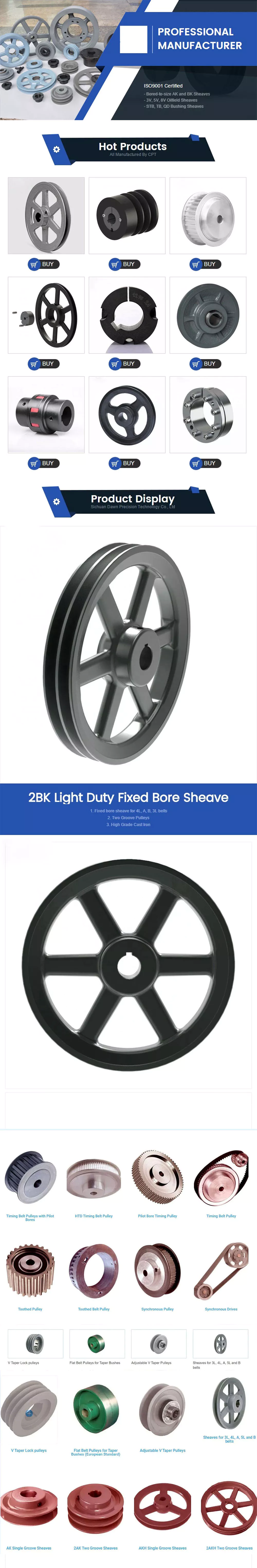
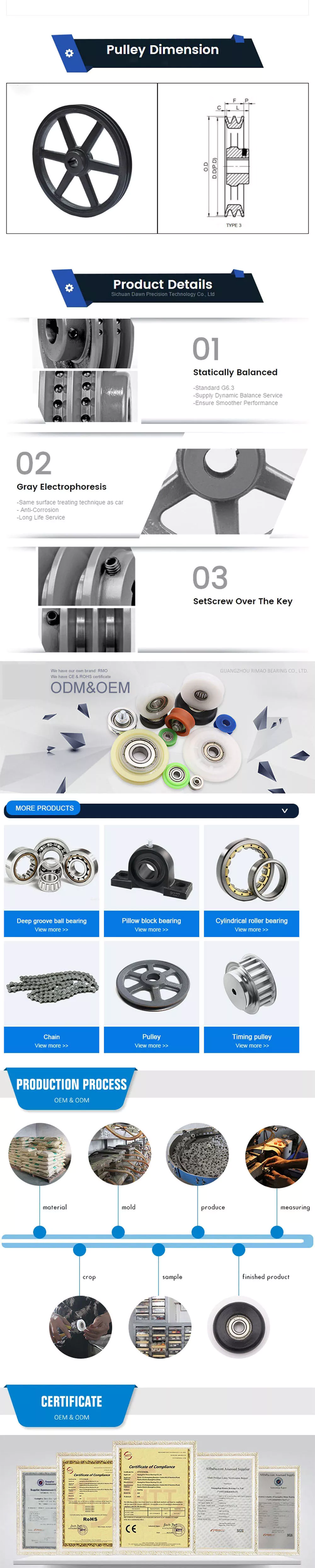
Flange Cast Iron Coupling Steel Universal Joint Cardan Pump Rubber Motor Disc CHINAMFG Flex Rigid Drive Shaft NM yox Fluid Jaw Flexible Chain Gear Couplings
Manufacturer of Couplings, Fluid Coupling, JAW Coupling, can interchange and replacement of lovejoy coupling and so on.
A coupling can interchange and replacement of lovejoy coupling is a device used to connect 2 shafts together at their ends for the purpose of transmitting power. The primary purpose of couplings is to join 2 pieces of rotating equipment while permitting some degree of misalignment or end movement or both. In a more general context, a coupling can also be a mechanical device that serves to connect the ends of adjacent parts or objects. Couplings do not normally allow disconnection of shafts during operation, however there are torque limiting couplings which can slip or disconnect when some torque limit is exceeded. Selection, installation and maintenance of couplings can lead to reduced maintenance time and maintenance cost.
Coupling is a jaw type coupling that works for a variety of light duty to heavy duty motors used in electric power transmission.
This is 1 of our safest types of products. The reason being that these couplings work even when the elastomer fails and there is no metal to metal contact.
They perform in well-standing oil, grease, moisture, sand, and dirt and nearly 850,000 bore combinations that can be customised as per the customer’s needs.
They are used in light-weight, medium, or heavy electrical motors and devices for power transmission through internal combustion.
Production workshop:
Company information:
Maintenance Practices for Ensuring Cardan Coupling Reliability
To ensure the reliability of cardan couplings, the following maintenance practices are crucial:
- Lubrication: Regularly inspect and maintain the lubrication system. Ensure proper lubricant levels and use lubricants recommended by the manufacturer.
- Alignment: Maintain proper alignment between the input and output shafts. Misalignment can lead to premature wear and reduced efficiency.
- Regular Inspections: Perform visual inspections to detect signs of wear, damage, or corrosion. Regular inspections can help identify issues before they become major problems.
- Monitoring: Use sensors and monitoring systems to track the performance of the cardan coupling. Monitor temperature, vibration, and other parameters for anomalies.
- Torque Analysis: Analyze the torque requirements of the machinery system to ensure that the cardan coupling can handle the load without exceeding its limits.
- Periodic Maintenance: Follow the manufacturer’s recommended maintenance schedule. This may include replacing worn components, lubricant changes, and alignment adjustments.
- Record Keeping: Maintain detailed maintenance records, including inspection dates, lubrication schedules, and any repairs performed.
- Training: Ensure that maintenance personnel are trained to properly inspect, maintain, and troubleshoot cardan couplings.
By implementing these maintenance practices, operators can extend the lifespan of cardan couplings, prevent unexpected failures, and optimize the performance of machinery systems.
Challenges and Alignment of Cardan Couplings
Cardan couplings, while capable of accommodating angular misalignment, can pose certain challenges related to alignment. Here’s an overview of these challenges and how they can be addressed:
1. Angular Misalignment Limit: Cardan couplings have a limit to the amount of angular misalignment they can accommodate without causing excessive wear and vibration. It’s essential to stay within the manufacturer’s specified misalignment range.
2. Precision Assembly: Assembling a cardan coupling requires precision to ensure that the yokes and spider are aligned correctly. Misaligned assembly can lead to premature wear and increased vibrations.
3. Balancing and Vibration: Cardan couplings can introduce imbalances due to their design. Imbalances can result in vibration and reduce the overall efficiency of the system.
4. Lubrication: Adequate lubrication is crucial to minimize friction and wear in the bearings of the spider. Poor lubrication can lead to increased heat generation and accelerated wear.
5. Maintenance: Regular maintenance is required to monitor the condition of the coupling, including checking for wear, misalignment, and any signs of damage.
6. Torque Fluctuation: In applications with significant angular misalignment, cardan couplings may experience torque fluctuations due to the changing angles of the shafts.
To address these challenges:
– Follow the manufacturer’s guidelines for installation, alignment, and maintenance.
– Use precision tools and techniques during assembly to ensure proper alignment.
– Balance the rotating components to minimize vibration.
– Maintain proper lubrication to reduce friction and wear.
– Periodically inspect the coupling for wear, misalignment, and signs of damage.
– Consider using flexible couplings with higher misalignment capabilities for applications with extreme misalignment requirements.
Proper alignment, maintenance, and adherence to manufacturer recommendations can help maximize the efficiency and longevity of cardan couplings in mechanical systems.

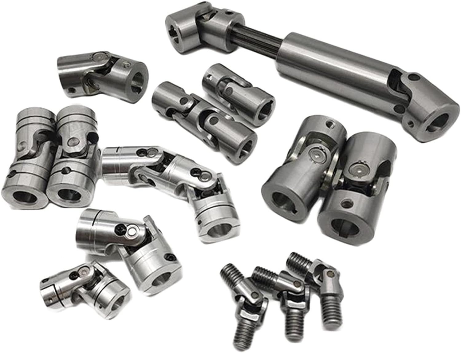
Are there different types of cardan couplings for various applications?
Yes, there are different types of cardan couplings designed to suit various applications and requirements:
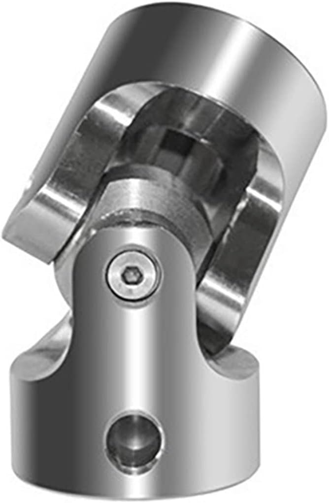
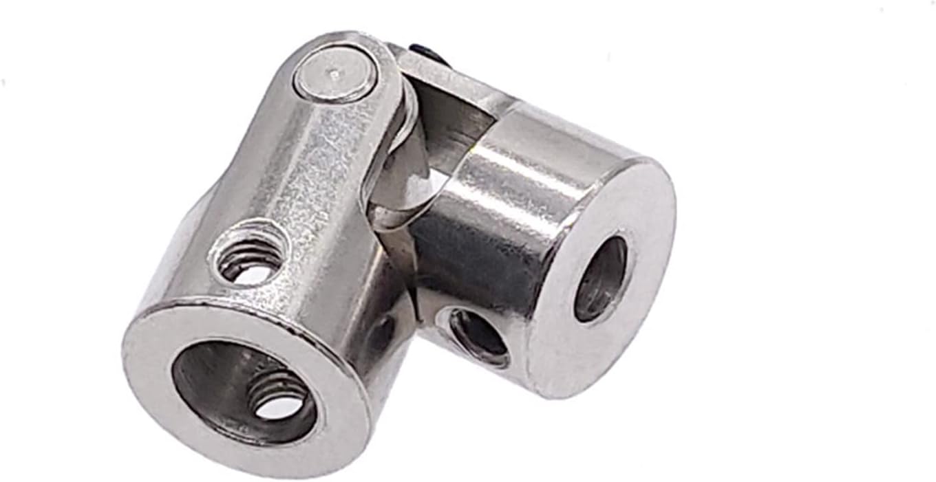
- Single Universal Joint: This is the most common type of cardan coupling, consisting of two yokes connected by a cross-shaped center piece. It is suitable for applications where angular misalignment compensation is needed, but the shafts are not too far apart.
- Double Cardan Joint: Also known as a double U-joint or CV joint, this type consists of two universal joints connected by an intermediate shaft. It is used when higher angles of misalignment need to be accommodated or when a constant velocity transmission is required.
- Disc Type Coupling: This type uses flexible discs or plates to transmit torque and compensate for misalignment. It is often used in applications with limited space and moderate torque requirements.
- Block Type Coupling: Block type cardan couplings use solid blocks or spheres to transmit torque. They are suitable for heavy-duty applications and can handle higher torque loads.
- Floating Shaft Coupling: This design involves two shafts connected by a third floating shaft, which allows for even higher angles of misalignment and smoother torque transmission.
- Needle Bearing Universal Joint: In this type, needle bearings are used to reduce friction and improve efficiency. It is often used in precision applications where low friction and high efficiency are crucial.
The choice of cardan coupling type depends on factors such as the amount of misalignment, torque requirements, available space, and the need for constant velocity transmission. Selecting the right type ensures optimal performance and longevity in various mechanical systems.


editor by CX 2023-11-07
China Good quality Flange Cast Iron Coupling Steel Universal Joint Cardan Pump Rubber Motor Disc Curved Tooth Flex Rigid Drive Shaft Nm Yox Fluid Jaw Flexible Chain Gear Couplings
Product Description
Flange Cast Iron Coupling Steel Universal Joint Cardan Pump Rubber Motor Disc CZPT Flex Rigid Drive Shaft NM yox Fluid Jaw Flexible Chain Gear Couplings
Manufacturer of Couplings, Fluid Coupling, JAW Coupling, can interchange and replacement of lovejoy coupling and so on.
A coupling can interchange and replacement of lovejoy coupling is a device used to connect 2 shafts together at their ends for the purpose of transmitting power. The primary purpose of couplings is to join 2 pieces of rotating equipment while permitting some degree of misalignment or end movement or both. In a more general context, a coupling can also be a mechanical device that serves to connect the ends of adjacent parts or objects. Couplings do not normally allow disconnection of shafts during operation, however there are torque limiting couplings which can slip or disconnect when some torque limit is exceeded. Selection, installation and maintenance of couplings can lead to reduced maintenance time and maintenance cost.
Coupling is a jaw type coupling that works for a variety of light duty to heavy duty motors used in electric power transmission.
This is 1 of our safest types of products. The reason being that these couplings work even when the elastomer fails and there is no metal to metal contact.
They perform in well-standing oil, grease, moisture, sand, and dirt and nearly 850,000 bore combinations that can be customised as per the customer’s needs.
They are used in light-weight, medium, or heavy electrical motors and devices for power transmission through internal combustion.
Production workshop:
Company information:
Recent Technological Advancements in Cardan Coupling Design
In recent years, there have been notable advancements and innovations in the design of cardan couplings:
- Material Enhancements: Advances in materials science have led to the development of high-strength and lightweight materials that can improve the performance and durability of cardan couplings.
- Sealing Technology: Improved sealing mechanisms and materials help prevent contamination and enhance the lifespan of cardan couplings.
- Computer-Aided Design (CAD): CAD software allows for more precise and optimized design of cardan couplings, leading to better performance and reduced stress concentrations.
- Finite Element Analysis (FEA): FEA techniques enable engineers to simulate the behavior of cardan couplings under various loads and conditions, aiding in design optimization.
- Lubrication Systems: Innovations in lubrication systems ensure efficient and consistent lubrication, reducing wear and enhancing coupling longevity.
- Monitoring and Diagnostics: Integration of sensors and monitoring systems enables real-time data collection for performance analysis, predictive maintenance, and early detection of issues.
- Customization: Advanced manufacturing techniques allow for more customization, making it possible to design cardan couplings tailored to specific applications.
These advancements contribute to the overall efficiency, reliability, and performance of cardan couplings, making them more suitable for a wide range of applications.
Handling High Torque and Axial Displacement with Cardan Couplings
Cardan couplings, also known as universal joints or u-joints, are designed to transmit torque between two shafts that are not in a straight line. They are versatile components commonly used in various applications, including those requiring high torque and axial displacement.
Handling High Torque: Cardan couplings are capable of handling high levels of torque transmission due to their robust design and construction. The design allows for torque to be transmitted through a series of interconnected components, including the cross-shaped yokes and the bearing assemblies. The use of high-strength materials and precision manufacturing techniques contributes to the coupling’s ability to transmit torque efficiently.
Handling Axial Displacement: While cardan couplings are primarily designed for accommodating angular misalignment, they can also handle a certain degree of axial displacement. Axial displacement refers to the movement of the connected shafts along their axis. However, the axial displacement capacity of a cardan coupling is limited compared to its ability to handle angular misalignment.
It’s important to note that excessive torque or axial displacement beyond the coupling’s design limits can lead to premature wear, increased vibrations, and reduced performance. Manufacturers provide specifications and guidelines for the maximum torque and axial displacement that a specific cardan coupling can handle. Engineers and designers should adhere to these specifications to ensure optimal performance and longevity of the coupling in their applications.
Factors to Consider When Selecting a Cardan Coupling for Specific Applications
Choosing the right cardan coupling for a specific application requires careful consideration of various factors:
- Torque and Power Transmission: Determine the required torque and power capacity of the coupling to ensure it can handle the intended load without exceeding its limits.
- Angular Misalignment: Assess the level of angular misalignment that might occur between the connected shafts and choose a coupling that can accommodate it without causing excessive wear or vibration.
- Operating Speed: Consider the rotational speed of the shafts to ensure that the coupling’s design can handle the desired speed without causing issues like resonance or fatigue.
- Environmental Conditions: Evaluate the operating environment, including factors like temperature, humidity, and exposure to contaminants, to select a coupling made from materials that can withstand these conditions.
- Shaft Sizes and Types: Measure the diameter and type of shafts that need to be connected and choose a coupling with compatible dimensions and attachment methods.
- Space Constraints: Consider the available space for the coupling within the machinery and select a compact design that fits without causing interference.
- Maintenance Requirements: Evaluate the maintenance practices and frequency that will be feasible for your application and choose a coupling that aligns with those requirements.
- Cost and Budget: Factor in the cost of the coupling and its potential impact on your budget while ensuring that the chosen coupling meets your performance needs.
- Shock and Vibration: Determine if the application involves high levels of shock or vibration and select a coupling that can absorb or mitigate these forces to prevent premature failure.
- Life Cycle and Reliability: Consider the expected lifespan of the machinery and choose a coupling that offers the desired level of durability and reliability.
By carefully considering these factors, you can select the most suitable cardan coupling for your specific application, ensuring optimal performance and longevity.
editor by CX 2023-08-11
China OEM Stainless Steel Nonstandard Woodon China Disc Couplings Universal Coupling SWC-I120b-295, SWC-I100dh-304+30, SWC-I120b-295 wholesaler
Product Description
| Product Name | Cardan Shaft |
| Product Model | SWC-I75A-335+40 |
| Main Material | 35CrMo or 45# Steel |
| Nominal Torque | 500 N.M |
| Normal Length | 335 mm |
| Length Compensation | 40 mm |
| Standard Or Nonstandard: | Nonstandard |
|---|---|
| Shaft Hole: | 19-32 |
| Torque: | >80N.M |
| Bore Diameter: | 19mm |
| Speed: | 4000r/M |
| Structure: | Flexible |
| Samples: |
US$ 10/Piece
1 Piece(Min.Order) | |
|---|
| Customization: |
Available
| Customized Request |
|---|

What Is a Coupling?
A coupling is a device used to connect two shafts. It transmits power between them and allows for some misalignment or end movement. There are several types of couplings. The most common ones are gear couplings and planetary couplings. However, there are many others as well.
Transfer of energy
Energy coupling is a process by which two biological reactions are linked by sharing energy. The energy released during one reaction can be used to drive the second. It is a very useful mechanism that synchronizes two biological systems. All cells have two types of reactions, exergonic and endergonic, and they are connected through energy coupling.
This process is important for a number of reasons. The first is that it allows the exchange of electrons and their energy. In a single molecule, this energy transfer involves the exchange of two electrons of different energy and spin. This exchange occurs because of the overlap interaction of two MOs.
Secondly, it is possible to achieve quadratic coupling. This is a phenomenon that occurs in circular membrane resonators when the system is statically deflected. This phenomenon has been gaining a great deal of interest as a mechanism for stronger coupling. If this mechanism is employed in a physical system, energy can be transferred on a nanometer scale.
The magnetic field is another important factor that affects the exchange of energy between semiconductor QWs. A strong magnetic field controls the strength of the coupling and the energy order of the exciton. The magnetic field can also influence the direction of polariton-mediated energy transfer. This mechanism is very promising for controlling the routing of excitation in a semiconductor.
Functions
Couplings play a variety of functions, including transferring power, compensating for misalignment, and absorbing shock. These functions depend on the type of shaft being coupled. There are four basic types: angular, parallel, and symmetrical. In many cases, coupling is necessary to accommodate misalignment.
Couplings are mechanical devices that join two rotating pieces of equipment. They are used to transfer power and allow for a small degree of end-to-end misalignment. This allows them to be used in many different applications, such as the transmission from the gearbox to the differential in an automobile. In addition, couplings can be used to transfer power to spindles.
Types
There are two main types of couplings: rigid and flexible. Rigid couplings are designed to prevent relative motion between the two shafts and are suitable for applications where precise alignment is required. However, high stresses in the case of significant misalignment can cause early failure of the coupling. Flexible couplings, on the other hand, allow for misalignment and allow for torque transmission.
A software application may exhibit different types of coupling. The first type involves the use of data. This means that one module may use data from another module for its operation. A good example of data coupling is the inheritance of an object. In a software application, one module can use another module’s data and parameters.
Another type of coupling is a rigid sleeve coupling. This type of coupling has a pipe with a bore that is finished to a specified tolerance. The pipe contains two threaded holes for transmitting torque. The sleeve is secured by a gib head key. This type of coupling may be used in applications where a couple of shafts are close together.
Other types of coupling include common and external. Common coupling occurs when two modules share global data and communication protocols. This type of coupling can lead to uncontrollable error propagation and unforeseen side effects when changes are made to the system. External coupling, on the other hand, involves two modules sharing an external device interface or communication protocol. Both types of coupling involve a shared code structure and depend on the external modules or hardware.
Mechanical couplings are essential in power transmission. They connect rotating shafts and can either be rigid or flexible, depending on the accuracy required. These couplings are used in pumps, compressors, motors, and generators to transmit power and torque. In addition to transferring power, couplings can also prevent torque overload.
Applications
Different coupling styles are ideal for different applications, and they have different characteristics that influence the coupling’s reliability during operation. These characteristics include stiffness, misalignment capability, ease of installation and maintenance, inherent balance, and speed capability. Selecting the right coupling style for a particular application is essential to minimize performance problems and maximize utility.
It is important to know the requirements for the coupling you choose before you start shopping. A proper selection process takes into account several design criteria, including torque and rpm, acoustic signals, and environmental factors. Once you’ve identified these parameters, you can select the best coupling for the job.
A gear coupling provides a mechanical connection between two rotating shafts. These couplings use gear mesh to transmit torque and power between two shafts. They’re typically used on large industrial machines, but they can also be used in smaller motion control systems. In smaller systems, a zero-backlash coupling design is ideal.
Another type of coupling is the flange coupling. These are easy to manufacture. Their design is similar to a sleeve coupling. But unlike a sleeve coupling, a flange coupling features a keyway on one side and two threaded holes on the other. These couplings are used in medium-duty industrial applications.
Besides being useful for power transmission, couplings can also prevent machine vibration. If vibration occurs in a machine, it can cause it to deviate from its predetermined position, or damage the motor. Couplings, however, help prevent this by absorbing the vibration and shock and preventing damage to expensive parts.
Couplings are heavily used in the industrial machinery and electrical industries. They provide the necessary rotation mechanism required by machinery and other equipment. Coupling suppliers can help customers find the right coupling for a specific application.
Criteria for selecting a coupling
When selecting a coupling for a specific application, there are a number of different factors to consider. These factors vary greatly, as do operating conditions, so selecting the best coupling for your system can be challenging. Some of these factors include horsepower, torque, and speed. You also need to consider the size of the shafts and the geometry of the equipment. Space restrictions and maintenance and installation requirements should also be taken into account. Other considerations can be specific to your system, such as the need for reversing.
First, determine what size coupling you need. The coupling’s size should be able to handle the torque required by the application. In addition, determine the interface connection, such as straight or tapered keyed shafts. Some couplings also feature integral flange connections.
During the specification process, be sure to specify which materials the coupling will be made of. This is important because the material will dictate most of its performance characteristics. Most couplings are made of stainless steel or aluminum, but you can also find ones made of Delrin, titanium, or other engineering-grade materials.
One of the most important factors to consider when selecting a coupling is its torque capability. If the torque rating is not adequate, the coupling can be damaged or break easily. Torque is a major factor in coupling selection, but it is often underestimated. In order to ensure maximum coupling performance, you should also take into consideration the size of the shafts and hubs.
In some cases, a coupling will need lubrication throughout its lifecycle. It may need to be lubricated every six months or even once a year. But there are couplings available that require no lubrication at all. An RBI flexible coupling by CZPT is one such example. Using a coupling of this kind can immediately cut down your total cost of ownership.
editor by CX 2023-07-12
China Stainless Steel 304 Silica Sol Investment Casting Quick Couplings for Valve Parts excitation contraction coupling
Merchandise Description
Item Particulars
| Process | Investment decision Casting+machining+sharpening |
| Material | ss316,ss304 and so forth. As consumers ask for. |
| Casting Tolerance | CT4-9 for stainless steel precision casting provider |
| Floor Treatment method | Sharpening,Plating,Powder coating and so on. As consumers request |
| Quality Handle | Strictly one hundred% Inspection |
| Support | Custom-made stainless steel precision casting service |
| Packing | picket box/pallet, with big plastic bag inside of |
| Guide Time | 30-35 for stainless steel precision casting |
Merchandise Display
| To Be Negotiated | 100 Pieces (Min. Order) |
###
| Casting Method: | Precision Investment Casting |
|---|---|
| Process: | Casting+CNC Machining |
| Molding Technics: | Silica Sol, Lost Wax |
| Application: | Valve Parts |
| Material: | 304 316 Stainless Steel |
| Surface Preparation: | Sand Blast |
###
| Customization: |
Available
|
|---|
###
| Process | Investment Casting+machining+polishing |
| Material | ss316,ss304 etc. As customers request. |
| Casting Tolerance | CT4-9 for stainless steel precision casting service |
| Surface Treatment | Polishing,Plating,Powder coating etc. As customers request |
| Quality Control | Strictly 100% Inspection |
| Service | Customized stainless steel precision casting service |
| Packing | wooden box/pallet, with big plastic bag inside |
| Lead Time | 30-35 for stainless steel precision casting |
What Is a Coupling?
A coupling is a mechanical device that links two shafts together and transmits power. Its purpose is to join rotating equipment while permitting a small amount of misalignment or end movement. Couplings come in a variety of different types and are used in a variety of applications. They can be used in hydraulics, pneumatics, and many other industries.
Types
Coupling is a term used to describe a relationship between different modules. When a module depends on another, it can have different types of coupling. Common coupling occurs when modules share certain overall constraints. When this type of coupling occurs, any changes to the common constraint will also affect the other modules. Common coupling has its advantages and disadvantages. It is difficult to maintain and provides less control over the modules than other types of coupling.
There are many types of coupling, including meshing tooth couplings, pin and bush couplings, and spline couplings. It is important to choose the right coupling type for your specific application to get maximum uptime and long-term reliability. Listed below are the differences between these coupling types.
Rigid couplings have no flexibility, and require good alignment of the shafts and support bearings. They are often used in applications where high torque is required, such as in push-pull machines. These couplings are also useful in applications where the shafts are firmly attached to one another.
Another type of coupling is the split muff coupling. This type is made of cast iron and has two threaded holes. The coupling halves are attached with bolts or studs.
Applications
The coupling function is an incredibly versatile mathematical tool that can be used in many different scientific domains. These applications range from physics and mathematics to biology, chemistry, cardio-respiratory physiology, climate science, and electrical engineering. The coupling function can also help to predict the transition from one state to another, as well as describing the functional contributions of subsystems in the system. In some cases, it can even be used to reveal the mechanisms that underlie the functionality of interactions.
The coupling selection process begins with considering the intended use of the coupling. The application parameters must be determined, as well as the operating conditions. For example, if the coupling is required to be used for power transmission, the design engineer should consider how easily the coupling can be installed and serviced. This step is vital because improper installation can result in a more severe misalignment than is specified. Additionally, the coupling must be inspected regularly to ensure that the design parameters remain consistent and that no detrimental factors develop.
Choosing the right coupling for your application is an important process, but it need not be difficult. To find the right coupling, you must consider the type of machine and environment, as well as the torque, rpm, and inertia of the system. By answering these questions, you will be able to select the best coupling for your specific application.
Problems
A coupling is a device that connects two rotating shafts to transfer torque and rotary motion. To achieve optimal performance, a coupling must be designed for the application requirements it serves. These requirements include service, environmental, and use parameters. Otherwise, it can prematurely fail, causing inconvenience and financial loss.
In order to prevent premature failure, couplings should be properly installed and maintained. A good practice is to refer to the specifications provided by the manufacturer. Moreover, it is important to perform periodic tests to evaluate the effectiveness of the coupling. The testing of couplings should be performed by qualified personnel.
editor by czh 2022-12-21
China Flexible Couplings
Flexible Couplings
How to tell if your driveshaft needs replacing
What is the cause of the unbalanced drive shaft? Unstable U-joint? Your car may make clicking noises while driving. If you can hear it from both sides, it might be time to hand it over to the mechanic. If you’re not sure, read on to learn more. Fortunately, there are many ways to tell if your driveshaft needs replacing.
unbalanced
An unbalanced driveshaft can be the source of strange noises and vibrations in your vehicle. To fix this problem, you should contact a professional. You can try a number of things to fix it, including welding and adjusting the weight. The following are the most common methods. In addition to the methods above, you can use standardized weights to balance the driveshaft. These standardized weights are attached to the shaft by welders.
An unbalanced drive shaft typically produces lateral vibrations per revolution. This type of vibration is usually caused by a damaged shaft, missing counterweights, or a foreign object stuck on the drive shaft. On the other hand, torsional vibrations occur twice per revolution, and they are caused by shaft phase shifts. Finally, critical speed vibration occurs when the RPM of the drive shaft exceeds its rated capacity. If you suspect a driveshaft problem, check the following:
Manually adjusting the imbalance of a drive shaft is not the easiest task. To avoid the difficulty of manual balancing, you can choose to use standardized weights. These weights are fixed on the outer circumference of the drive shaft. The operator can manually position the weight on the shaft with special tools, or use a robot. However, manual balancers have many disadvantages.
unstable
When the angular velocity of the output shaft is not constant, it is unstable. The angular velocity of the output shaft is 0.004 at ph = 29.5 and 1.9 at t = 1.9. The angular velocity of the intermediate shaft is not a problem. But when it’s unstable, the torque applied to it is too much for the machine. It might be a good idea to check the 10sion on the shaft.
An unstable drive shaft can cause a lot of noise and mechanical vibration. It can lead to premature shaft fatigue failure. CZPT studies the effect of shaft vibration on the rotor bearing system. They investigated the effect of flex coupling misalignment on the vibration of the rotor bearing system. They assume that the vibrational response has 2 components: x and y. However, this approach has limited application in many situations.
Experimental results show that the presence of cracks in the output shaft may mask the unbalanced excitation characteristics. For example, the presence of superharmonic peaks on the spectrum is characteristic of cracks. The presence of cracks in the output shaft masks unbalanced excitation characteristics that cannot be detected in the transient response of the input shaft. Figure 8 shows that the frequency of the rotor increases at critical speed and decreases as the shaft passes the natural frequency.
Unreliable
If you’re having trouble driving your car, chances are you’ve run into an unreliable driveshaft. This type of drivetrain can cause the wheels to stick or not turn at all, and also limit the overall control of the car. Whatever the reason, these issues should be resolved as soon as possible. Here are some symptoms to look for when diagnosing a driveshaft fault. Let’s take a closer look.
The first symptom you may notice is an unreliable drive shaft. You may feel vibrations, or hear noises under the vehicle. Depending on the cause, it could be a broken joint or a broken shaft. The good news is that driveshaft repairs are generally relatively inexpensive and take less time than a complete drivetrain replacement. If you’re not sure what to do, CZPT has a guide to replacing the U-connector.
One of the most common signs of an unreliable driveshaft is clanging and vibration. These sounds can be caused by worn bushings, loose U-joints, or damaged center bearings. This can cause severe vibration and noise. You can also feel these vibrations through the steering wheel or the floor. An unreliable driveshaft is a symptom of a bigger problem.
Unreliable U-joints
A car with an unreliable U-joint on the drive shaft can be dangerous. A bad u-joint can prevent the vehicle from driving properly and may even cause you trouble. Unreliable u-joints are cheap to replace and you should try getting parts from quality manufacturers. Unreliable U-joints can cause the car to vibrate in the chassis or gear lever. This is a sure sign that your car has been neglected in maintenance.
Replacing a U-joint is not a complicated task, but it requires special tools and a lot of elbow grease. If you don’t have the right tools, or you’re unfamiliar with mechanical terminology, it’s best to seek the help of a mechanic. A professional mechanic will be able to accurately assess the problem and propose an appropriate solution. But if you don’t feel confident enough, you can replace your own U-connector by following a few simple steps.
To ensure the vehicle’s driveshaft is not damaged, check the U-joint for wear and lubrication. If the U-joint is worn, the metal parts are likely to rub against each other, causing wear. The sooner a problem is diagnosed, the faster it can be resolved. Also, the longer you wait, the more you lose on repairs.
damaged drive shaft
The driveshaft is the part of the vehicle that connects the wheels. If the driveshaft is damaged, the wheels may stop turning and the vehicle may slow down or stop moving completely. It bears the weight of the car itself as well as the load on the road. So even a slight bend or break in the drive shaft can have dire consequences. Even a piece of loose metal can become a lethal missile if dropped from a vehicle.
If you hear a screeching noise or growl from your vehicle when shifting gears, your driveshaft may be damaged. When this happens, damage to the u-joint and excessive slack in the drive shaft can result. These conditions can further damage the drivetrain, including the front half. You should replace the driveshaft as soon as you notice any symptoms. After replacing the driveshaft, you can start looking for signs of wear.
A knocking sound is a sign of damage to the drive shaft. If you hear this sound while driving, it may be due to worn couplings, damaged propshaft bearings, or damaged U-joints. In some cases, the knocking noise can even be caused by a damaged U-joint. When this happens, you may need to replace the entire driveshaft, requiring a new 1.
Maintenance fees
The cost of repairing a driveshaft varies widely, depending on the type and cause of the problem. A new driveshaft costs between $300 and $1,300, including labor. Repairing a damaged driveshaft can cost anywhere from $200 to $300, depending on the time required and the type of parts required. Symptoms of a damaged driveshaft include unresponsiveness, vibration, chassis noise and a stationary car.
The first thing to consider when estimating the cost of repairing a driveshaft is the type of vehicle you have. Some vehicles have more than 1, and the parts used to make them may not be compatible with other cars. Even if the same car has 2 driveshafts, the damaged 1s will cost more. Fortunately, many auto repair shops offer free quotes to repair damaged driveshafts, but be aware that such work can be complicated and expensive.


China PIN Couplings
PIN Couplings
What Is a Worm Gear Reducer?
If you have never seen a worm gear reducer before, you’re missing out! Learn more about these incredible gears and their applications by reading this article! In addition to worm gear reducers, learn about worms and how they’re made. You’ll also discover what types of machines can benefit from worm gears, such as rock crushers and elevators. The following information will help you understand what a worm gear reducer is and how to find 1 in your area.
Typical worm shaft
A typical worm has 2 shafts, 1 for advancing and 1 for receding, which form the axial pitch of the gear. Usually, there are 8 standard axial pitches, which establish a basic dimension for worm production and inspection. The axial pitch of the worm equals the circular pitch of the gear in the central plane and the master lead cam’s radial pitch. A single set of change gears and 1 master lead cam are used to produce each size of worm.
Worm gear is commonly used to manufacture a worm shaft. It is a reliable and efficient gear reduction system that does not move when the power is removed. Typical worm gears come in standard sizes as well as assisted systems. Manufacturers can be found online. Listed below are some common materials for worm gears. There are also many options for lubrication. The worm gear is typically made from case hardened steel or bronze. Non-metallic materials are also used in light-duty applications.
A self-locking worm gear prevents the worm from moving backwards. Typical worm gears are generally self-locking when the lead angle is less than 11 degrees. However, this feature can be detrimental to systems that require reverse sensitivity. If the lead angle is less than 4 degrees, back-driving is unlikely. However, if fail-safe protection is a prerequisite, back-driving worm gears must have a positive brake to avoid reverse movement.
Worm gears are often used in transmission applications. They are a more efficient way to reduce the speed of a machine compared to conventional gear sets. Their reduced speed is possible thanks to their low ratio and few components. Unlike conventional gear sets, worm gears require less maintenance and lower mechanical failure than a conventional gear set. While they require fewer parts, worm gears are also more durable than conventional gear sets.
There are 2 types of worm tooth forms. Convex and involute helicoids have different types of teeth. The former uses a straight line to intersect the involute worm generating line. The latter, on the other hand, uses a trapezoid based on the central cross section of the root. Both of these tooth forms are used in the production of worms. And they have various variations in pitch diameter.
Types of worms
Worms have several forms of tooth. For convenience in production, a trapezoid-based tooth form is used. Other forms include an involute helicoidal or a convolute worm generating a line. The following is a description of each type. All types are similar, and some may be preferred over others. Listed below are the 3 most common worm shaft types. Each type has its own advantages and disadvantages.
Discrete versus parallel axis: The design of a worm gear determines its ratio of torque. It’s a combination of 2 different metals – 1 for the worm and 1 for the wheel – which helps it absorb shock loads. Construction equipment and off-road vehicles typically require varying torques to maneuver over different terrain. A worm gear system can help them maneuver over uneven terrain without causing excessive wear.
Worm gear units have the highest ratio. The sliding action of the worm shaft results in a high self-locking torque. Depending on the angle of inclination and friction, a worm gear can reach up to 100:1! Worm gears can be made of different materials depending on their inclination and friction angle. Worm gears are also useful for gear reduction applications, such as lubrication or grinding. However, you should consider that heavier gears 10d to be harder to reverse than lighter 1s.
Metal alloy: Stainless steel, brass, and aluminum bronze are common materials for worm gears. All 3 types have unique advantages. A bronze worm gear is typically composed of a combination of copper, zinc, and tin. A bronze shaft is more corrosive than a brass 1, but it is a durable and corrosion-resistant option. Metal alloys: These materials are used for both the worm wheel.
The efficiency of worm gears depends on the assembly conditions and the lubricant. A 30:1 ratio reduces the efficiency to 81:1%. A worm gear is more efficient at higher ratios than an helical gear, but a 30:1 ratio reduces the efficiency to 81%. A helical gear reduces speed while preserving torque to around 15% of the original speed. The difference in efficiency between worm gear and helical gear is about half an hour!
Methods of manufacturing worm shafts
Several methods of manufacturing worm shafts are available in the market. Single-pointed lathe tools or end mills are the most popular methods for manufacturing worms. These tools are capable of producing worms with different pressure angles depending on their diameter, the depth of thread, and the grinding wheel’s diameter. The diagram below shows how different pressure angles influence the profile of worms manufactured using different cutting tools.
The method for making worm shafts involves the process of establishing the proper outer diameter of a common worm shaft blank. This may include considering the number of reduction ratios in a family, the distance between the worm shaft and the gear set center, as well as the torques involved. These processes are also referred to as ‘thread assembly’. Each process can be further refined if the desired axial pitch can be achieved.
The axial pitch of a worm must match the circular pitch of the larger gear. This is called the pitch. The pitch diameter and axial pitch must be equal. Worms can be left-handed or right-handed. The lead, which refers to the distance a point on the thread travels during 1 revolution of the worm, is defined by its angle of tangent to the helix on the pitch of the cylinder.
Worm shafts are commonly manufactured using a worm gear. Worm gears can be used in different applications because they offer fine adjustment and high gear reduction. They can be made in both standard sizes and assisted systems. Worm shaft manufacturers can be found online. Alternatively, you can contact a manufacturer directly to get your worm gears manufactured. The process will take only a few minutes. If you are looking for a manufacturer of worm gears, you can browse a directory.
Worm gears are made with hardened metal. The worm wheel and gear are yellow in color. A compounded oil with rust and oxidation inhibitors is also used to make worm gears. These oils adhere to the shaft walls and make a protective barrier between the surfaces. If the compounded oil is applied correctly, the worm gear will reduce the noise in a motor, resulting in a smoother performance.
applications for worm gear reducers
Worm gears are widely used in power transmission applications, providing a compact, high reduction, low-speed drive. To determine the torque ratio of worm gears, a numerical model was developed that makes use of the equation of displacement compatibility and the influence coefficient method, which provides fast computing. The numerical model also incorporates bending deflections of the gear surfaces and the mating surfaces. It is based on the Boussinesq theory, which calculates local contact deformations.
Worm gears can be designed to be right or left-handed, and the worm can turn either clockwise or counter-clockwise. An internal helical gear requires the same hand to operate both parts. In contrast, an external helical gear must be operated by the opposite hand. The same principle applies to worm gears in other applications. The torque and power transferred can be large, but worm gears are able to cope with large reductions in both directions.
Worm gears are extremely useful in industrial machinery designs. They reduce noise levels, save space, and give machines extra precision and fast-stopping capabilities. Worm gears are also available in compact versions, making them ideal for hoisting applications. This type of gear reducer is used in industrial settings where space is an issue. Its smaller size and less noise makes it ideal for applications that need the machine to stop quickly.
A double-throated worm gear offers the highest load capacity while still remaining compact. The double-throated version features concave teeth on both worm and gear, doubling the contact area between them. Worm gears are also useful for low to moderate-horsepower applications, and their high ratios, high output torque, and significant speed reduction make them a desirable choice for many applications. Worm gears are also quieter than other types of gears, reducing the noise and vibrations that they cause.
Worm gears have numerous advantages over other types of gears. They have high levels of conformity and can be classified as a screw pair within a lower-pair gear family. Worm gears are also known to have a high degree of relative sliding. Worm gears are often made of hardened steel or phosphor-bronze, which provides good surface finish and rigid positioning. Worm gears are lubricated with special lubricants that contain surface-active additives. Worm gear lubrication is a mixed lubrication process and causes mild wear and tear.
China PIN Couplings
PIN Couplings
The benefits of using pulleys
A pulley is a mechanical device that converts force into rotation. There are many advantages to using pulleys. Let’s take a look at a few of them. This article will describe the advantages, types, applications, and power sources of pulleys. You can then choose the pulley that best suits your specific needs. If you’re looking for a new tool to help you with a certain task, this article is for you.
Mechanical advantage
The mechanical advantage of a pulley can be defined as the ratio of applied force to the applied force. The mechanical advantage of a pulley can be calculated by considering several factors, including weight and friction. It can be calculated by the force applied per unit length of rope and the number of pulleys used. In a single-circuit system, the force required to lift a heavy object is equal to the user’s body weight.
The mechanical advantage of a pulley can be realized by comparing it to a seesaw. Both uses of rope are suitable for lifting objects. A rope 4 times heavier than a kilo is 4 times as effective. Because the forces on both sides of the pulley are equal, a small force is enough to move a large weight a short distance. The same force can be applied to a large mass to lift it several meters.
After introducing the concept of mechanical advantage, learners will practice using the pulley system. In addition to testing the pulley system, they should also calculate its mechanical advantage. Using either the instructor-provided handout or the learner’s workbook, students will determine how easily the pulley system functions. Once they have completed the test, they can discuss their results and how the system can be improved. These courses are best completed as part of a mini-unit or as a standalone main course.
The mechanical advantage of the pulley system is proportional to the number of rope loops. This circuit requires the same force as the dual circuit to lift heavy objects. A single lap requires only a third of the force to lift a double lap, while 3 laps require almost half the energy required for a single lap. The mechanical advantage of the pulley system becomes constant as the number of cycles increases.
The 3:1 Mechanical Advantage system feels like lifting a 300-pound load with 3 feet of rope. The 3-foot-long rope moves the load 1 foot high. Understanding the mechanical advantages of pulleys is critical for rescuers when trying to create the perfect pulley system. Ideally, the pulley system will be anchored to a nearby rock, tree, pole or person – if the weight is not too heavy.
Types of pulleys
There are several types of pulleys. V-belt pulleys are the type commonly used in vehicles and electric motors. “V” pulleys require a “V” belt, and some even have multiple V grooves. “V” pulleys are often used in heavy duty applications for power transmission because they reduce the risk of power slippage.
Composite pulleys combine the properties of fixed and movable pulleys. Compound pulleys are able to change the direction of force while requiring relatively low force to move even the heaviest loads. Mechanical advantage is a measure of the effectiveness of a machine or equipment. It can be divided into 3 categories: force, distance and mechanics. Once you understand how each type works, you can design complex machines.
Fixed pulleys: These pulleys are the most basic type of pulleys. They use ropes and slotted wheels to move with the lifted object. Because they are so simple to set up, lifting heavy objects is a breeze. Although the moving object feels light, it is actually heavier than it actually is. These pulleys are used in construction cranes, utility elevators and many different industries.
Compound Pulley System: A pulley pulley is a combination of 2 fixed pulleys and 1 movable pulley. Compound pulley systems are effective for moving heavy objects because they have the largest force multipliers and are flexible enough to change the direction of the force as needed. Composite pulley systems are commonly used in rock climbing, theater curtains and sailing. If you’re looking for a pulley system, you can start by evaluating the types of pulleys and their uses.
Construction Pulleys: These are the most basic types of pulleys and have wheel rails. These pulleys can be lifted to great heights and attached to chains or ropes. They allow workers to access equipment or materials from greater heights. They are usually mounted on wheels with axles and secured with ropes. They are essential tools for construction workers. There are many different types of pulleys out there.
energy source
Belts and pulleys are mechanical devices used to transmit energy and rotational motion. The belt is connected to the rotating part of the energy source, and the pulley is mounted on the other. One pulley transmits power to the other, while the other changes the direction of the force. Many devices use this combination, including automobiles, stationary generators, and winches. It is used in many home applications, from conveyors to treadmills. Pulleys are also used for curtains in theater halls.
Pulley systems are an essential part of modern industry and everyday life. Pulleys are used in elevators, construction sites and fitness equipment. They are also used in belt-driven generators as backup power. Despite their simple and seemingly humble beginnings, they have become a versatile tool. From lifting heavy objects to guiding wind turbines, pulley systems are widely used in our daily lives.
The main reason why pulleys are so popular is the mechanical advantage they offer. They can lift a lot of weight by applying very little force over longer distances. For example, a small motor can pull 10 meters of cable, while a large motor can pull 1 meter. Also, the work done is equal to the force times the distance traveled, so the energy delivered to the large motor is the same.
The power source for the pulley system can be cables, belts or ropes. The drive element in a pulley system is usually a rope or cable. A belt is a loop of flexible material that transmits motion from 1 pulley to another. The belt is attached to the shaft and a groove is cut in the pulley. The belt then transfers energy from 1 pulley to the other through the system.
application
A pulley is a mechanical device used to lift heavy objects. They reduce the amount of work required to lift heavy objects and are an excellent choice for many applications. There are several different applications for pulleys, including elevators, grinders, planters, ladder extensions, and mountaineering or rock climbing. Let’s take a look at some of the most popular uses for pulleys in modern society. These include:-
A pulley is a mechanical device that changes force. To use, you wrap the rope around it and pull down to lift the object. While this device is very useful, a major limitation of using pulleys is that you still have to apply the same force to lift the object as you would without the pulleys. This is why people use pulleys to move large objects like furniture and cars.
In addition to lifting heavy objects, pulleys are used in elevators, flagpoles and wells. These systems allow people to move heavy objects without straining their backs. Many other examples of pulleys in the home include garage doors, flagpoles, and elevators. They also help raise and lower flagpoles, which can reach several stories high.
There are 2 basic types of pulleys: movable and fixed. Fixed pulleys are attached to a ceiling or other object using 2 ropes. Modern elevators and construction cranes use movable pulleys, as do some weight machines in gyms. Composite pulleys combine movable and fixed pulleys to minimize the force required to move heavy objects.
Another type of fixed pulley is the flagpole. A flagpole can support a country, organization, or anything else that needs to be lifted. A taller flagpole creates a prouder moment for those who support it. The operation of the rope and pulley mechanism is very simple. The user simply attaches the flag to the rope, pulls the pulley, and he or she can watch the flag rise and unfold.