Product Description
Who we are?
HangZhou XIHU (WEST LAKE) DIS. CARDANSHAFT CO;LTD has 15 years history.When the general manager Mr.Rony Du graduated from the university,he always concentrated his attention on the research and development,production and sales of the cardan shaft.Mr.Rony Du and his team started from scratch,from 1 lathe and a very small order,step by step to grow up.He often said to his team”We will only do 1 thing well——to make the perfect cardan shaft”.
HangZhou XIHU (WEST LAKE) DIS. CARDANSHAFT CO.,LTD was founded in 2005.The registered capital is 8 million ,covers an area of 15 acres, has 30 existing staff. The company specializing in the production of SWC, SWP cross universal coupling and drum tooth coupling.The company with factory is located in the beautiful coast of Tai Lake –Hudai (HangZhou Economic Development Zone Hudai Industrial Park).
In order to become China’s leading cardan shaft one-stop solution expert supplier .XIHU (WEST LAKE) DIS. CARDANSHAFT independent research and development of SWC light, medium, short, heavy Designs cardan shaft have reached the leading domestic level.Products not only supporting domestic large and medium-sized customers, but also exported to the United States, India, Vietnam, Laos, Ukraine, Russia, Germany, Britain and other countries and areas.In the past 15 years, the company has accumulated a wealth of experience, learn from foreign advanced technology, and to absorb and use the universal axis has been improved several times, so that the structure is maturing, significantly improved performance.
XIHU (WEST LAKE) DIS. belief: “Continuous innovation, optimize the structure, perseverance” to create a high quality of outstanding cardan shaft manufacturer.We always adhere to the ISO9001 quality control system, from the details to start, standardize the production process, and to achieve processing equipment “specialization, numerical control” rapid increase in product quality.This Not only won the majority of customers reputation, but also access to peer recognition. We continue to strive to pursue: “for customers to create the greatest value, for the staff to build the best platform”, will be able to achieve customer and business mutually beneficial CHINAMFG situation.
Why choose us?
First,select raw material carefully
The cross is the core component of cardan shaft,so the selection of material is particularly critical.Raw materials of the cross for light Duty Size and Medium Duty Size,we choose the 20CrMnTi special gear steel bar from SHAGANG GROUP.Being forged in 2500 ton friction press to ensure internal metallurgical structure,inspecting the geometric dimensions of each part to meet the drawing requirements,then transfer to machining,the processes of milling, turning, quenching and grinding.
The inspector will screen blank yoke head.The porosity, cracks, slag, etc. do not meet the requirements of the casting foundry are all eliminated,then doing physical and chemical analysis, to see whether the ingredients meet the requirements, unqualified re-elimination.And then transferred to the quenching and tempering heat treatment, once again check the hardness to see if meet the requirements, qualified to be transferred to the machining process. We control from the source of the material to ensure the supply of raw materials qualified rate of 99%.
Second,advanced production equipment
XIHU (WEST LAKE) DIS. Company introduced four-axis linkage machining center made in ZheJiang , milling the keyway and flange bolt hole of the flange yoke, The once machine-shaping ensures that the symmetry of the keyway and the position of the bolt hole are less than 0.02mm,which greatly improves the installation accuracy of the flange,the 4 axis milling and drilling center holes of the cross are integrated,to ensure that the 4 shaft symmetry and verticality are less than 0.02mm,the process of the journal cross assembly service life can be increased by 30%, and the speed at 1000 rpm above the cardan shaft running smoothly and super life is crucial to the operation.
We use CNC machine to lathe flange yoke and welded yoke,CNC machine can not only ensure the accuracy of the flange connection with the mouth, but also improve the flange surface finish.
5 CHINAMFG automatic welding machine welding spline sleeve and tube,welded yoke and tube.With the welding CHINAMFG swing mechanism, automatic lifting mechanism, adjustment mechanism and welding CHINAMFG cooling system, welding machine can realize multi ring continuous welding, each coil current and voltage can be preset, arc starting and stopping control PLC procedures, reliable welding quality, the weld bead is smooth and beautiful, to control the welding process with fixed procedures, greatly reducing the uncertainty of human during welding, greatly improve the welding effect.
High speed cardan shaft needs to do dynamic balance test before leaving the factory.Unbalanced cardan shaft will produce excessive centrifugal force at high speed and reduce the service life of the bearing;the dynamic balance test can eliminate the uneven distribution of the casting weight and the mass distribution of the whole assembly;Through the experiment to achieve the design of the required balance quality, improve the universal shaft service life.In 2008 the company introduced 2 high-precision dynamic balance test bench, the maximum speed can reach 4000 rev / min, the balance of G0.8 accuracy, balance weight 2kg–1000kg.
In order to make the paint standardization, in 2009 the company bought 10 CHINAMFG of clean paint room , the surface treatment of cardan shaft is more standardized, paint fastness is more rugged, staff’s working conditions improved, exhaust of harmless treatment.
Third,Professional transport packaging
The packing of the export cardan shaft is all in the same way as the plywood wooden box, and then it is firmly secured with the iron sheet, so as to avoid the damage caused by the complicated situation in the long-distance transportation. Meet the standard requirements of plywood boxes into Europe and other countries, no matter where can successfully reach all the country’s ports.
The following table for SWC Medium-sized Universal Shaft Parameters.
Designs
Data and Sizes of SWC Series Universal Joint Couplings
| pe | Design Data Item |
SWC160 | SWC180 | SWC200 | SWC225 | SWC250 | SWC265 | SWC285 | SWC315 | SWC350 | SWC390 | SWC440 | SWC490 | SWC550 | SWC620 |
| A | L | 740 | 800 | 900 | 1000 | 1060 | 1120 | 1270 | 1390 | 1520 | 1530 | 1690 | 1850 | 2060 | 2280 |
| LV | 100 | 100 | 120 | 140 | 140 | 140 | 140 | 140 | 150 | 170 | 190 | 190 | 240 | 250 | |
| M(kg) | 65 | 83 | 115 | 152 | 219 | 260 | 311 | 432 | 610 | 804 | 1122 | 1468 | 2154 | 2830 | |
| B | L | 480 | 530 | 590 | 640 | 730 | 790 | 840 | 930 | 100 | 1571 | 1130 | 1340 | 1400 | 1520 |
| M(kg) | 44 | 60 | 85 | 110 | 160 | 180 | 226 | 320 | 440 | 590 | 820 | 1090 | 1560 | 2100 | |
| C | L | 380 | 420 | 480 | 500 | 560 | 600 | 640 | 720 | 782 | 860 | 1040 | 1080 | 1220 | 1360 |
| M(kg) | 35 | 48 | 66 | 90 | 130 | 160 | 189 | 270 | 355 | 510 | 780 | 970 | 1330 | 1865 | |
| D | L | 520 | 580 | 620 | 690 | 760 | 810 | 860 | 970 | 1030 | 1120 | 1230 | 1360 | 1550 | 1720 |
| M(kg) | 48 | 65 | 90 | 120 | 173 | 220 | 250 | 355 | 485 | 665 | 920 | 1240 | 1765 | 2390 | |
| E | L | 800 | 850 | 940 | 1050 | 1120 | 1180 | 1320 | 1440 | 1550 | 1710 | 1880 | 2050 | 2310 | 2540 |
| LV | 100 | 100 | 120 | 140 | 140 | 140 | 140 | 140 | 150 | 170 | 190 | 190 | 240 | 250 | |
| M(kg) | 70 | 92 | 126 | 165 | 238 | 280 | 340 | 472 | 660 | 886 | 1230 | 1625 | 2368 | 3135 | |
| Tn(kN·m) | 16 | 22.4 | 31.5 | 40 | 63 | 80 | 90 | 125 | 180 | 250 | 355 | 500 | 710 | 1000 | |
| TF(kN·m) | 8 | 11.2 | 16 | 20 | 31.5 | 40 | 45 | 63 | 90 | 125 | 180 | 250 | 355 | 500 | |
| Β(°) | 15 | 15 | 15 | 15 | 15 | 15 | 15 | 15 | 15 | 15 | 15 | 15 | 15 | 15 | |
| D | 160 | 180 | 200 | 225 | 250 | 265 | 285 | 315 | 350 | 390 | 440 | 490 | 550 | 620 | |
| Df | 160 | 180 | 200 | 225 | 250 | 265 | 285 | 315 | 350 | 3690 | 440 | 490 | 550 | 620 | |
| D1 | 137 | 155 | 170 | 196 | 218 | 233 | 245 | 280 | 310 | 345 | 390 | 435 | 492 | 555 | |
| D2(H9) | 100 | 105 | 120 | 135 | 150 | 160 | 170 | 185 | 210 | 235 | 255 | 275 | 320 | 380 | |
| D3 | 108 | 114 | 140 | 159 | 168 | 180 | 194 | 219 | 245 | 273 | 299 | 325 | 402 | 426 | |
| Lm | 95 | 105 | 110 | 125 | 140 | 150 | 160 | 180 | 195 | 215 | 260 | 270 | 305 | 340 | |
| K | 16 | 17 | 18 | 20 | 25 | 25 | 27 | 32 | 35 | 40 | 42 | 47 | 50 | 55 | |
| T | 4 | 5 | 5 | 5 | 6 | 6 | 7 | 8 | 8 | 8 | 10 | 12 | 12 | 12 | |
| N | 8 | 8 | 8 | 8 | 8 | 8 | 8 | 10 | 10 | 10 | 16 | 16 | 16 | 16 | |
| D | 15 | 17 | 17 | 17 | 19 | 19 | 21 | 23 | 23 | 25 | 28 | 31 | 31 | 38 | |
| B | 20 | 24 | 32 | 32 | 40 | 40 | 40 | 40 | 50 | 70 | 80 | 90 | 100 | 100 | |
| G | 6.0 | 7.0 | 9.0 | 9.0 | 12.5 | 12.5 | 12.5 | 15.0 | 16.0 | 18.0 | 20.0 | 22.5 | 22.5 | 25 | |
| MI(Kg) | 2.57 | 3 | 3.85 | 3.85 | 5.17 | 6 | 6.75 | 8.25 | 10.6 | 13 | 18.50 | 23.75 | 29.12 | 38.08 | |
| Size | M14 | M16 | M16 | M16 | M18 | M18 | M20 | M22 | M22 | M24 | M27 | M30 | M30 | M36 | |
| Tightening torque(Nm) | 180 | 270 | 270 | 270 | 372 | 372 | 526 | 710 | 710 | 906 | 1340 | 1820 | 1820 | 3170 |
1. Notations:
L=Standard length, or compressed length for designs with length compensation;
LV=Length compensation;
M=Weight;
Tn=Nominal torque(Yield torque 50% over Tn);
TF=Fatigue torque, I. E. Permissible torque as determined according to the fatigue strength
Under reversing loads;
Β=Maximum deflection angle;
MI=weight per 100mm tube
2. Millimeters are used as measurement units except where noted;
3. Please consult us for customizations regarding length, length compensation and
Flange connections.
(DIN or SAT etc. )
Brief Introduction
Processing flow
Why choose us!
Quality Control
Application
/* January 22, 2571 19:08:37 */!function(){function s(e,r){var a,o={};try{e&&e.split(“,”).forEach(function(e,t){e&&(a=e.match(/(.*?):(.*)$/))&&1
Phasing in Cardan Couplings and Its Impact on Performance
The concept of phasing in cardan couplings refers to the alignment of the universal joints’ yokes or flanges on the input and output shafts. Proper phasing is essential to minimize angular misalignment and maintain smooth rotational motion. When the yokes of the universal joints are not aligned correctly, it can result in uneven torque transmission, increased wear, and vibrations.
Phasing affects the performance of cardan couplings in several ways:
- Uniform Torque Transmission: Proper phasing ensures that torque is evenly distributed between the input and output shafts, reducing the risk of overloading individual universal joints.
- Reduced Vibrations: Correctly phased universal joints minimize angular misalignment, which helps reduce vibrations and noise in the machinery system.
- Extended Lifespan: Improved phasing leads to reduced wear and stress on the universal joint components, extending the overall lifespan of the coupling.
- Efficient Power Transmission: Proper phasing contributes to efficient power transmission by minimizing energy losses due to misalignment.
To achieve proper phasing, manufacturers often provide guidelines or marks on the coupling components to ensure accurate alignment. It’s essential to follow these guidelines during installation and any maintenance or adjustments to maintain optimal performance and reliability of the cardan coupling.
Comparison of Cardan Couplings with Other Flexible Couplings
Cardan couplings, universal joints, and gear couplings are all types of flexible couplings used to transmit torque while accommodating misalignment. Here’s how a cardan coupling compares to other flexible coupling types:
1. Cardan Couplings:
– Also known as shaft couplings or u-joints.
– Typically consist of two yokes connected by a cross-shaped component called a spider.
– Accommodate angular misalignment.
– Limited to relatively lower speeds and torques.
– Provide moderate torsional flexibility.
2. Universal Joints:
– Consist of two yokes connected by cross-shaped pins and bearings.
– Accommodate angular misalignment similar to cardan couplings.
– Can transmit higher torques than cardan couplings.
– Limited in their ability to handle axial and parallel misalignment.
– Used in various applications, including automotive and industrial equipment.
3. Gear Couplings:
– Feature toothed gears that mesh to transmit torque.
– Accommodate angular, axial, and parallel misalignment.
– Suitable for high-speed and high-torque applications.
– Provide high torsional rigidity and accurate torque transmission.
– Require proper lubrication and maintenance.
When comparing these coupling types:
– Cardan couplings are simple and cost-effective solutions for moderate torque and speed applications with angular misalignment.
– Universal joints are versatile but may have limitations in handling higher torques and other misalignment types.
– Gear couplings offer superior torque and misalignment handling but are more complex and may require more maintenance.
The choice of coupling type depends on the specific application’s torque, speed, misalignment, and precision requirements.

Are there different types of cardan couplings for various applications?
Yes, there are different types of cardan couplings designed to suit various applications and requirements:
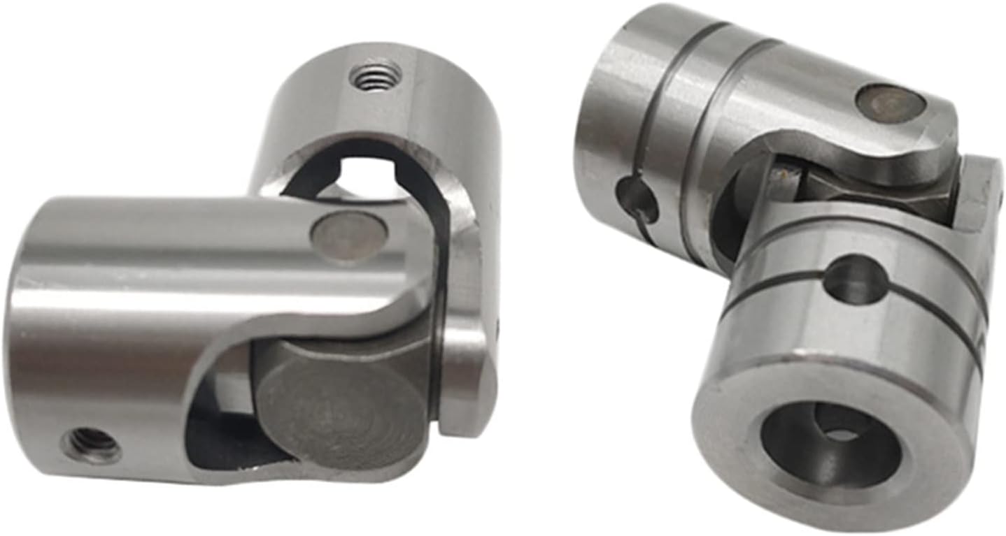
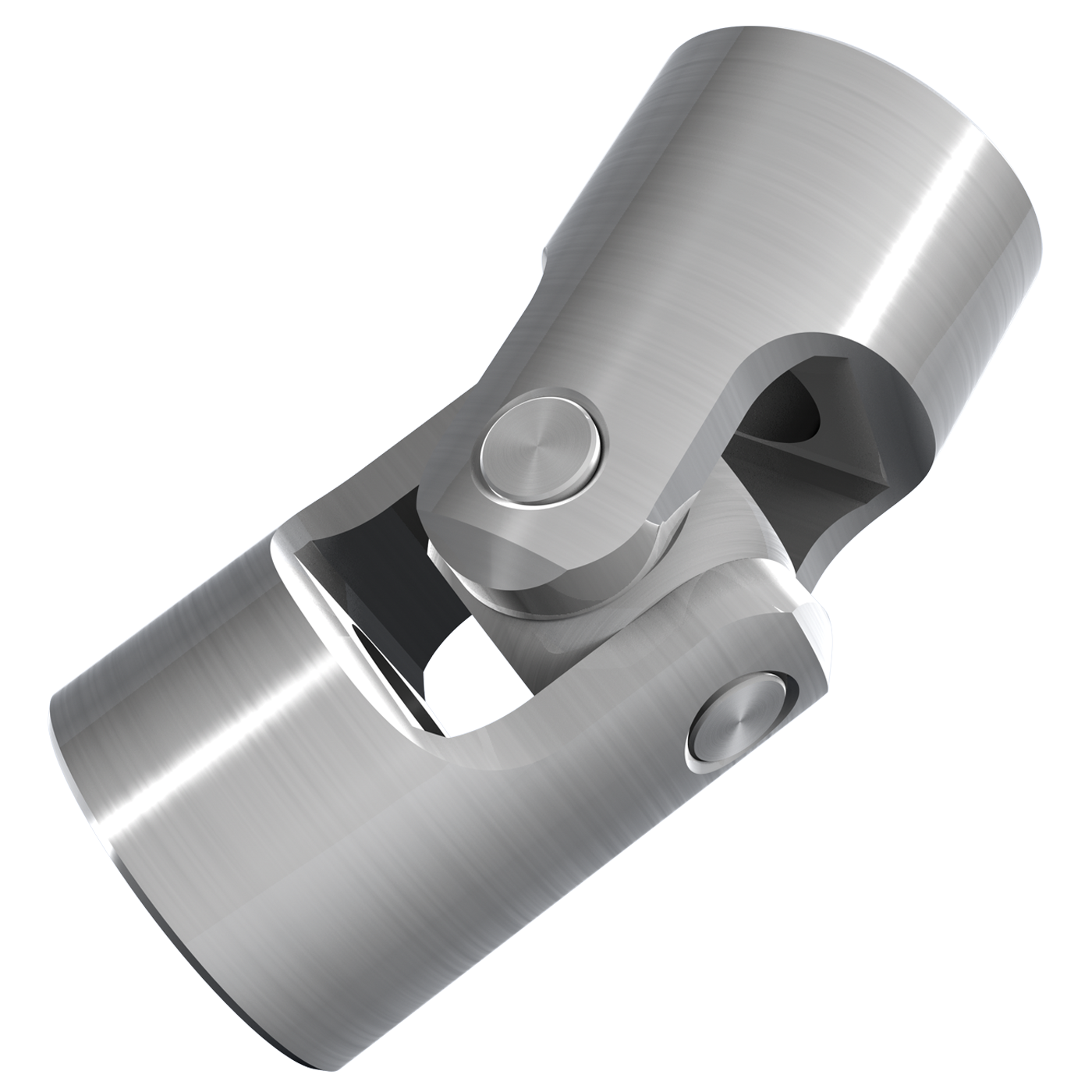
- Single Universal Joint: This is the most common type of cardan coupling, consisting of two yokes connected by a cross-shaped center piece. It is suitable for applications where angular misalignment compensation is needed, but the shafts are not too far apart.
- Double Cardan Joint: Also known as a double U-joint or CV joint, this type consists of two universal joints connected by an intermediate shaft. It is used when higher angles of misalignment need to be accommodated or when a constant velocity transmission is required.
- Disc Type Coupling: This type uses flexible discs or plates to transmit torque and compensate for misalignment. It is often used in applications with limited space and moderate torque requirements.
- Block Type Coupling: Block type cardan couplings use solid blocks or spheres to transmit torque. They are suitable for heavy-duty applications and can handle higher torque loads.
- Floating Shaft Coupling: This design involves two shafts connected by a third floating shaft, which allows for even higher angles of misalignment and smoother torque transmission.
- Needle Bearing Universal Joint: In this type, needle bearings are used to reduce friction and improve efficiency. It is often used in precision applications where low friction and high efficiency are crucial.
The choice of cardan coupling type depends on factors such as the amount of misalignment, torque requirements, available space, and the need for constant velocity transmission. Selecting the right type ensures optimal performance and longevity in various mechanical systems.


editor by CX 2024-04-09